
Small Circuits Revival – Episode 5
on
Simple Triac and Thyristor Tester
idea: Hans-Norbert Gerbig (Germany)
If you don't want to use an electromechanical relay to switch something on and off (see episode 3 of this series), then you can use a semiconductor alternative; if it only concerns small signals then this can be an ordinary transistor, and larger currents and voltages can be switched using by a (big) MOSFET, as outlined in Episode 2.
However, an elegant solution is offered by the now somewhat obscure thyristors and triacs. You can consider a thyristor as a diode that starts to conduct after receiving a pulse at its input called 'gate'. A thyristor only conducts in one direction (as expected from a well-behaved diode). A triac can be considered as two anti-parallel connected thyristors in one package, and is therefore suitable for alternating current.
Tester
Great, you have one of these parts in front of you, but before you intend to use it you'd like to know whether it still works – certainly if the part was salvaged from a discarded or trashed circuit (re-use is environmentally friendly!). Or perhaps you are not entirely sure whether it is actually a triac or a thyristor... In both cases the circuit in Figure 1 may prove useful.
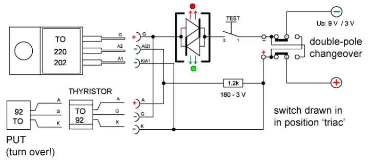
Admittedly, 'circuit' is a big word for two switches, a resistor and a bi-colour LED (red/green). It is not difficult to use: when either a triac or thyristor is connected and with the double-pole changeover switch (slide or toggle) in the position as drawn here, the LED will light up red after the Test button is pushed. When the switch is in the other position than drawn here and the Test button is pushed, the LED will light up green if a triac is connected; with a thyristor the LED remains off.
This tester can also be used to test devices called PUTs (Programmable Unijunction Transistor). With the switch in the ‘triac’ position (as it is drawn here) the LED remains off when pressing the button; with the switch in the other position the LED will light up green.
Note: the tester can be powered from either 9 V or 3 V. In the first case the resistor (which has no other function than keeping the current within limits) takes a value of 1.2 kΩ, in the second case, 180 Ω.
Simple? Simple!
Appeal
Have you invented a small circuit (preferably something using dead standard components that can be built on prototyping board), then send the schematic plus description to the Small Circuits Revival Editor! It won't make you rich, but eternal fame will be your reward...
Discussion (0 comments)