
Small Circuits Revival – Episode 8
on
Electronic Candle
idea: Elex Team
The candle presented here here does not use candle wax, wick, or a flickering flame, but instead a small, low-voltage incandescent lamp. Nevertheless: you certainly still have to ‘light’ the candle and you can also blow it out again... If you get started right away, you will be able to amaze your friends and family with this wonder candle this festive season.
The most important component in the schematic, shown in Figure 1, is resistor R1, a light-dependent resistor (LDR). This has the useful property that its resistance depends on the amount of incident light: the more light, the lower the resistance.
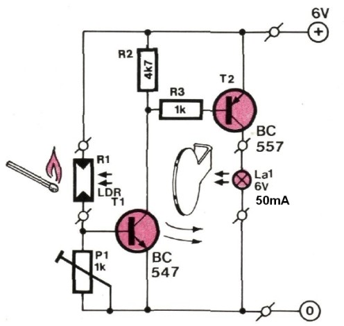
The LDR and trimpot P1 together form a potential divider. As soon as light from a match illuminates the LDR R1, its resistance will drop causing the voltage at the junction of R1 and P1 to rise – and with it the voltage at the base of T1, which subsequently will turn on. As a result, the voltage at the junction of R2 and R3 is pulled low, causing (pnp) transistor T2 to conduct as well. A current now flows through incandescent lamp La1 (a 6-V version that requires a current of only 50 mA) and which will then cheerfully light up. You can adjust the sensitivity of the circuit with P1.
The trick is, of course, that some light from the lamp is also 'seen' by the LDR, so that its resistance continues to be low, even after we have blown out the match. Voila, we have obtained a stable state.
Now the question that remains: how we can ‘blow out’ this candle? Well then: for this we use the mystery component that is drawn immediately to the left of lamp La1 in Figure 1. This is nothing more than an ordinary piece of paper positioned in such a way that you can blow it between the lamp and the LDR, which then causes a significant reduction in the amount of light detected by the LDR so that its resistance increases again, causing T1 and then also T2 to turn off – the lamp will go out.
As an aside: enthusiastic experimenters can try to build something using a temperature-sensitive resistor, which will cool down when blowing on it and will then have a different value....
Construction and power supply
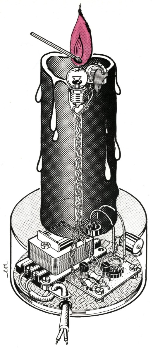
The drawing in Figure 2 offers an artist's impression of the construction. You can clearly see that the LDR and lamp have ‘visible contact’, and that the piece of paper after ‘blowing’ will darken the LDR.
For the power supply we recommend a set of four 1.5-V batteries. Draughtsman Laurent Martin has drawn a small mains power supply, with a transformer, bridge rectifier and a (fat) smoothing capacitor, but with hindsight and in view of safety that's not a good idea. Measuring by electronics standards, the circuit and black & white artwork have a respectable age of 36 years...
In any case: enjoy your tinkering!
Discussion (0 comments)