
CLUE from Adafruit: A Smart Solution for IoT Projects
on

The BBC micro:bit was a great success, far beyond the educational market it was intended for. Now, Adafruit's CLUE has entered the fray, complete with a fully-fledged display and far more memory. Complete with Bluetooth LE and a multitude of integrated sensors, it is especially suitable for smaller IoT projects.
Since the successes of Arduino and Raspberry Pi, it has become obvious that there is money to be made with educational computers of all kinds. In 2016, the BBC entered the race with the micro:bit, a single-board computer featuring a Bluetooth SoC from Nordic Semiconductor instead of a fully-fledged Linux-capable processor. Since then, incredible stories have emerged of businesses, such as Spy oz in Slovakia, who have built entire companies around the exclusive distribution of the micro:bit ecosystem [1].
The old saying that you “don’t eat at a well-filled pot all by yourself for too long” also applies to the field of embedded computing. The continued progress in the field of Bluetooth SoCs has led to the micro:bit’s 16 MHz and 16 kB SRAM looking a little long in the tooth. Moreover, its 5 × 5 LED display is not suited to outputting anything more than the simplest of graphics.
Adafruit Attacks with CLUE
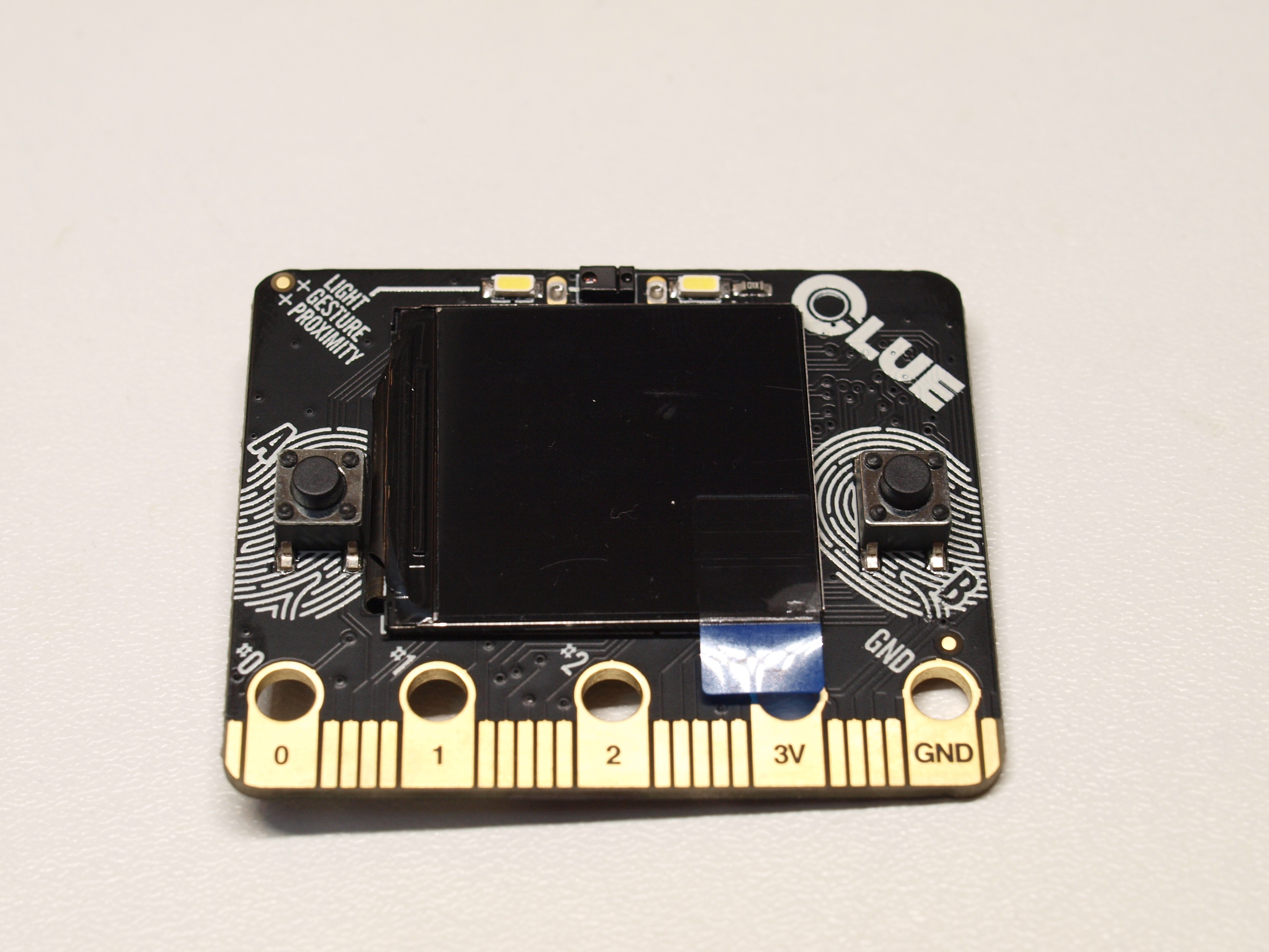
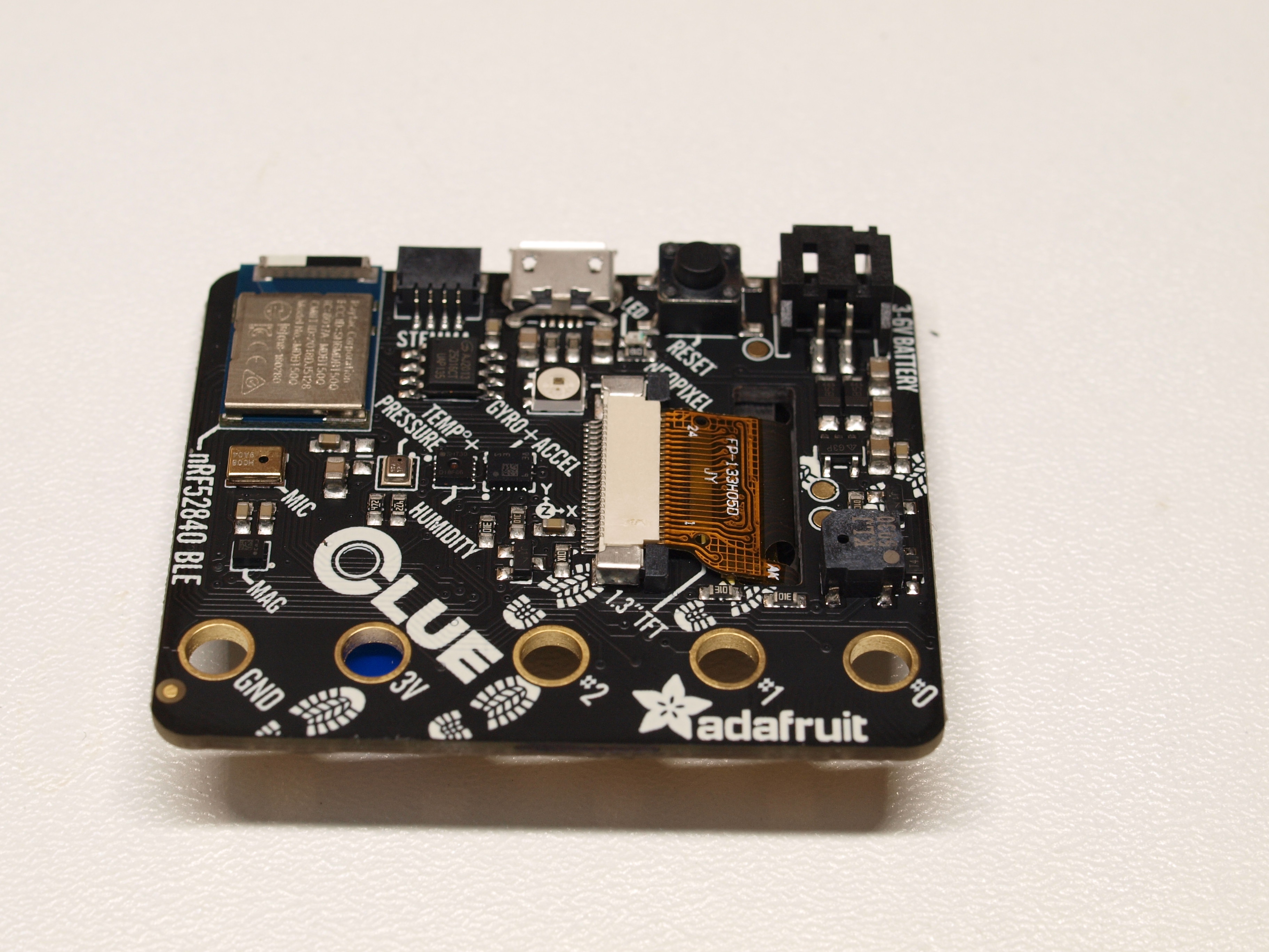
With the Nordic Semiconductor nRF52840 launch, a single-core Bluetooth SoC whose ARM processor reaches 64 MHz and featuring 256 kB RAM — an attack vector has opened. Figures 1 and Figure 2 show the result — the Adafruit CLUE that looks very similar to the BBC micro:bit. Besides the SoC, which is not immediately visible in these photos, it is the much larger screen on the front that really stands out. Instead of LEDs, we're given a 240 × 240-pixel color display based on classic IPS LCD rather than organic technology.
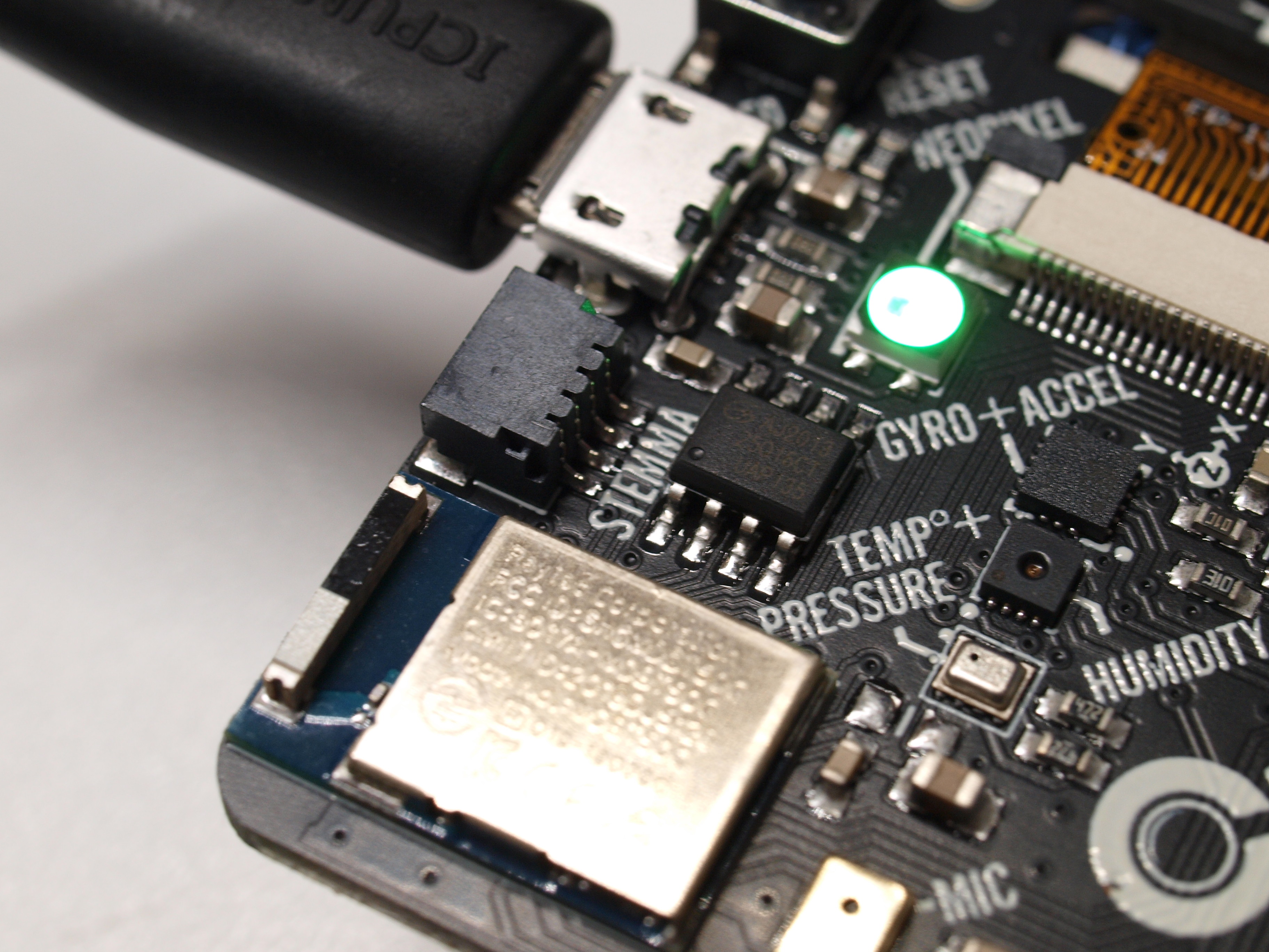
Another nice touch of the module is the connector located on the back, as shown in Figure 3. It exposes an I2C bus using Adafruit’s in-house format over which further sensors can be easily connected. There is also an adapter for the Grove format used by Seeed, from whom various reasonably-priced sensors are available.
It should be noted that the CLUE only looks to be partially compatible with its forebear. While the connector along the bottom edge is physically identical, using a different display means that, at first glance, it looked as though many of the available housings for the BBC micro:bit would not fit the Adafruit CLUE.
The author tested this hypothesis with a ThingiVerse case from domw available at [2]. The front obviously did not fit as the CLUE’s display was much larger than the LED matrix of the BBC’s original. Bearing this in mind, the author found it particularly surprising that the rear panel of the case fitted correctly, despite the additional connectors. However, on closer inspection, this was likely because the case design was comparatively generous. Had the case been designed with a tighter fit, it is unlikely to have been any use at all.
A Question of Programming
Being an educational system, developing with a micro:bit is unlike the experience to be had using classic embedded development environments such as ARM Keil. This may be annoying for embedded purists, but it is necessary in practice as many universities do not have enough competent personnel for debugging C++ (believe the author: students create some incredibly obtuse program errors).
Instead, it generally relies on a quadrumvirate of Arduino IDE, CircuitPython, MakeCode, and Scratch. For CLUE, however, only two of these environments are currently available. MakeCode is being worked on without a known delivery date, and there is no information on Scratch. What is included is a serial bootloader to enable the deployment of code, much like the Raspberry Pi Pico.
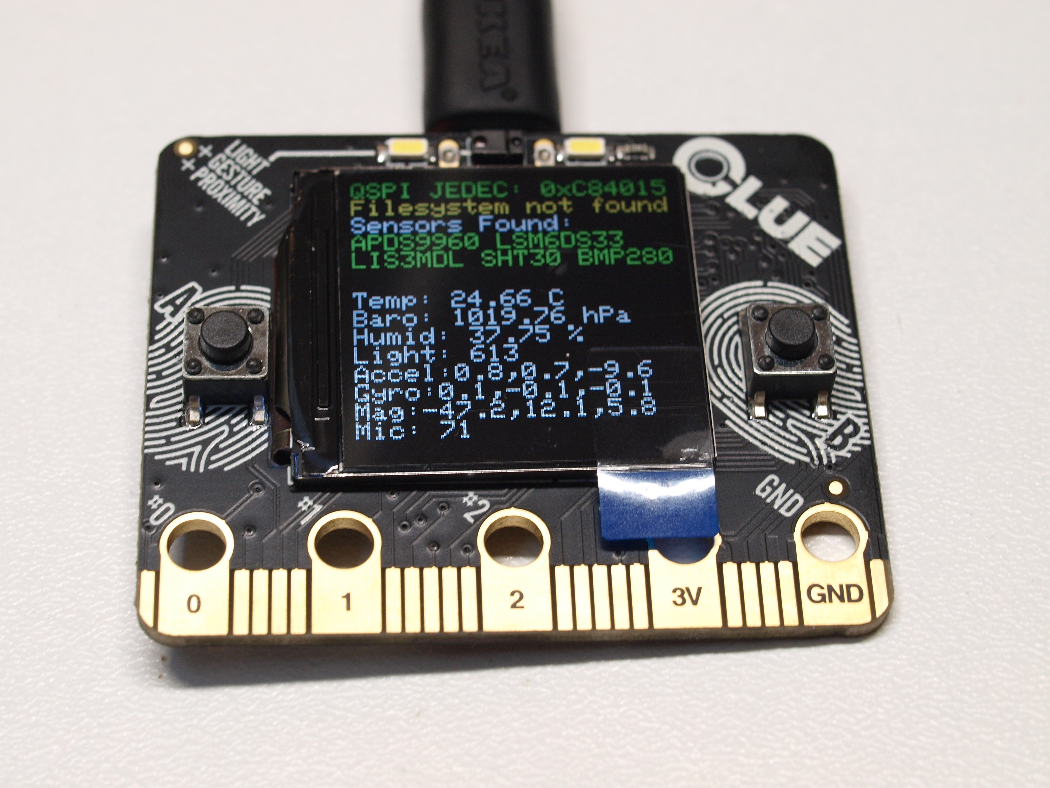
For a first, small experiment, let’s get CircuitPython running. If you connect a new board to the computer via the Micro-USB connector on the back, the display shows a status page (Figure 4) that provides information on the operating state.
Pressing the reset button on the back of the board twice initially causes the frame buffer in the screen's display controller to freeze. The connected workstation (the author runs Linux) then sees a new USB drive where compiled code can be uploaded.
Interestingly, the Adafruit CLUE is always visible to the computer. If it is not in bootloader mode, dmesg detects it as follows:
. . .
[28292.202193] usb 1-2.7: Manufacturer: Adafruit LLC
[28292.202195] usb 1-2.7: SerialNumber: 7687A137B6FDB874
[28292.204040] cdc_acm 1-2.7:1.0: ttyACM0: USB ACM device
After double-pressing the reset button, a USB drive appears instead, as shown here:
. . . .
[28371.624193] sd 10:0:0:0: Attached scsi generic sg6 type 0
It is important to note that this drive does not stay enabled forever. If it remains unused for more than 30 seconds or so, the firmware resets back to normal operation.
Search Files
By visiting the URL https://circuitpython.org/board/clue_nrf52840_express/, we can take our first step and download the adafruit-circuitpython-clue_nrf52840_express-en_US-6.1.0.uf2 file. This contains the runtime that must be placed on the USB drive.
It is interesting to note that you will also find a file called CURRENT.UF2 on the drive. This allows you to download the firmware that is currently in the memory of the target system.
Strangely, the runtime does not come with a full library that supports all the available sensors. Instead, we have to go to the URL https://circuitpython.org/libraries to download the archive adafruit-circuitpython-bundle-6.x-mpy-20210329.zip and then extract it to a convenient folder in the file system.
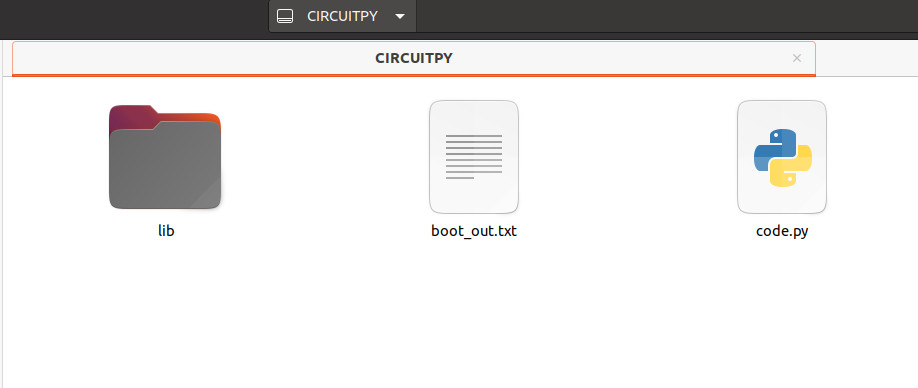
At this point, you should take another look at the CLUE’s screen as the runtime permanently outputs the console’s contents. A nice touch is that the device on the PC — as shown in Figure 5 — exposes the internal memory of the Python working environment.
It is important to place the following folders from the archive in the Libs folder on the device:
adafruit_bus_device
adafruit_display_shapes
adafruit_display_text
adafruit_lsm6ds
adafruit_register
As if this were not enough work, Adafruit also expects you to collect the following individual files. Why these are not all bundled up in a single archive is unclear:
adafruit_clue.mpy
adafruit_lis3mdl.mpy
adafruit_sht31d.mpy
adafruit_slideshow.mpy
neopixel.mpy
Code Example
For a first simple attempt with the Python environment, you can use the example provided at https://learn.adafruit.com/adafruit-clue/clue-spirit-level. This implements a spirit-level application using several CLUE-specific idioms.
The first step of the code is to include a group of libraries:
import displayio
from adafruit_display_shapes.circle import Circle
from adafruit_clue import clue
In addition to the clue object, which provides various board-related functions, the import of the Circle class is also interesting here. The GUI stack allows both direct drawing into a frame buffer as well as working with objects that are converted by the firmware into elements that appear on the screen.
In the next section, the firmware initializes a reference to the display and assembles a display group object:
clue_group = displayio.Group(max_size=4)
The clue_group object is interesting in that it generates a parent element reminiscent of a DOM tree. Our code then more or less writes arbitrary objects to this tree for display.
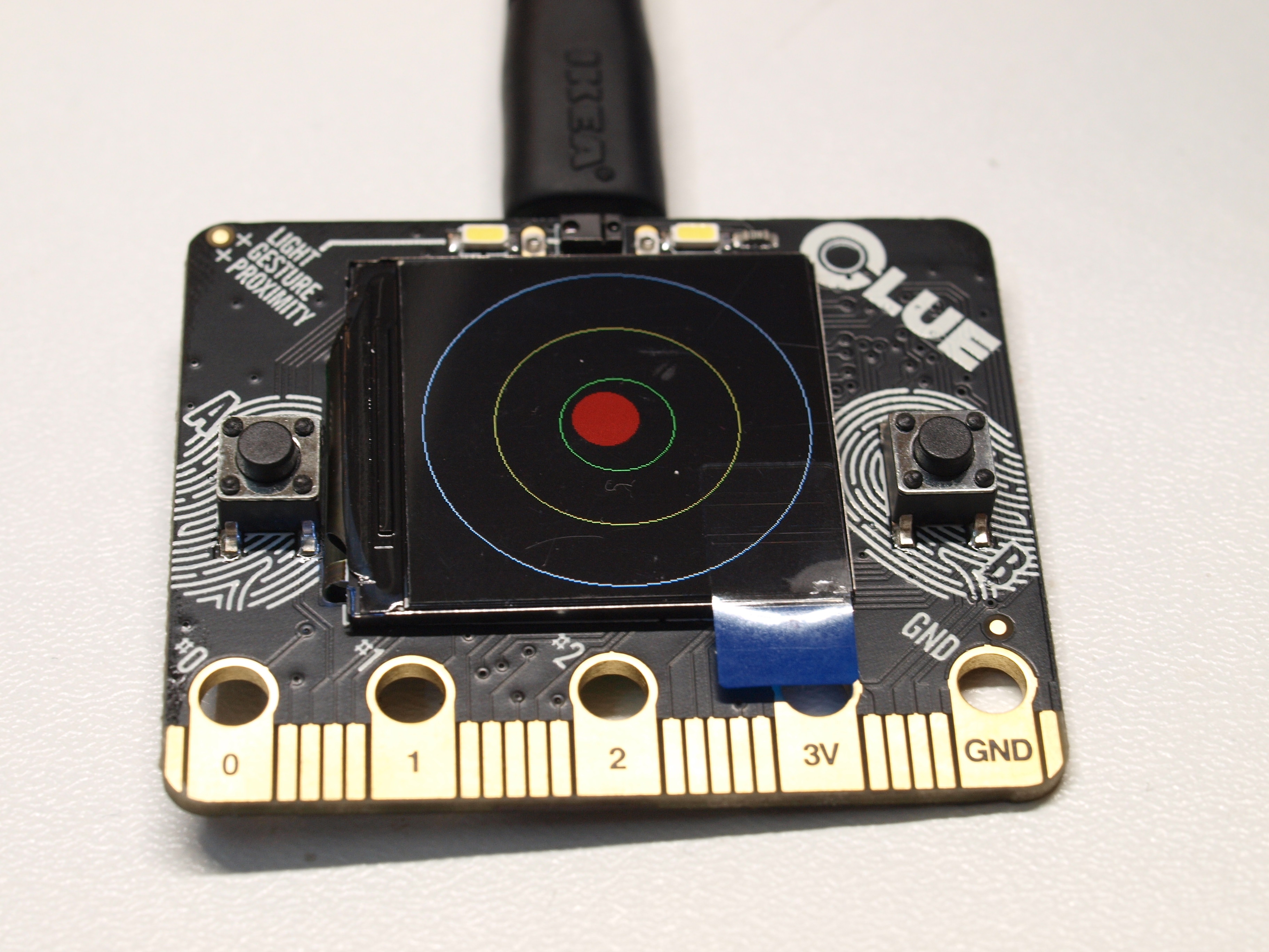
Looking at the image in Figure 6, it follows that the next step of the program is to generate the three circles responsible for the representation of the deflection and to register them for the output:
middle_circle = Circle(120, 120, 75, outline=clue.YELLOW)
inner_circle = Circle(120, 120, 35, outline=clue.GREEN)
clue_group.append(outer_circle)
clue_group.append(middle_circle)
clue_group.append(inner_circle)
Next are some more housekeeping tasks, the sense of which is most easily understood by examining the sample code below:
bubble_group = displayio.Group(max_size=1)
level_bubble = Circle(int(x + 120), int(y + 120), 20, fill=clue.RED, outline=clue.RED)
bubble_group.append(level_bubble)
clue_group.append(bubble_group)
display.show(clue_group)
Last but not least, we need a loop that analyzes the position values output by the Adafruit library via the acceleration attribute and writes them to the coordinate properties of the bubble_group object:
x, y, _ = clue.acceleration
bubble_group.x = int(x * -10)
bubble_group.y = int(y * -10)
The most convenient way to quickly execute code on the CLUE is to use the code.py file shown in Figure 5. The CircuitPython firmware automatically executes this as part of each startup. Figure 6 shows what you can expect.
Due to the presence of a Bluetooth radio, this can also be used to communicate with the host computer. At [3], Adafruit provides an entertaining example that illustrates the use of the web Bluetooth API implemented in Google Chrome.
And Now Using C
Python may be a fast way to get unbureaucratic results from an embedded system. However, maximum performance is achieved by using C. Especially on a single-core radio system, implementing communication is challenging if the application is not to be beset by timing problems. Because of this, Adafruit more or less forces developers to use the Arduino IDE. A real-time operating system then works in the background, allocating computing power to the various tasks.
Under Linux, the first step requires an extension package that allows the Arduino IDE (version 1.8.6 or higher) to communicate with the CLUE’s non-standard bootloader:
Collecting adafruit-nrfutil
. . .
Successfully installed adafruit-nrfutil-0.5.3.post13
Next, we need to enter the URL https://www.adafruit.com/package_adafruit_index.json in the Board Manager to make the Adafruit nRF52 board package available for download. After these steps are complete, the board is available under Tools > Board > Adafruit CLUE.
Unfortunately, as in the case of CircuitPython, setting up these libraries and other settings is a laborious process. More information on this can be found at [4].
CLUE: Is It Worth It?
If you do decide on the CLUE, you’re getting a thoroughly attractive evaluation platform that is pleasant to use in the area of interfacing coupled with the benefits of a color screen. On the other hand, the price is comparatively high compared to the BBC micro:bit, which costs considerably less. It should also be noted that the CLUE is not 100% compatible with the micro:bit. Experience tells us that this not insignificant detail has the greatest impact precisely when we are in difficultly, such as porting an existing, working project between the two platforms.
For those who want to work with a clean, Nordic-based microcontroller or radio module, you’ll probably be better served by a classic evaluation board. So the bottom line is that the CLUE is an endearing product for those who want to benefit from a BBC micro:bit but require a little more performance or use of a full display.
Questions or Comments About CLUE?
Do you have technical questions or comments about this article? Contact the Elektor team at editor@elektor.com.
Discussion (0 comments)