
Get to Know the Raspberry Pi Compute Module 4
on
The Raspberry Pi Compute Module 4 (CM4) has arrived. It has a new form factor and new peripherals, but will it make a good compute module, too? In combination with the Raspberry Pi Compute Module IO Board, this forms new possibilities to create Raspberry Pi-powered systems that were not possible with older modules. With the added PCI Express interface, you can now choose from high-speed peripherals to be combined with the RPi.
What is the Raspberry Pi Compute Module 4?
Rumors have been around for a while, and now we have the official proof of a Raspberry Pi 4-based compute module — Raspberry Pi Compute Module 4. The Compute Module is a stripped-down Raspberry Pi-based module intended to be incorporated into other products that need more design flexibility than the usual Raspberry Pi can offer. Also, it enables you to tightly integrate custom electronics around the Raspberry Pi SOC (e.g., for industrial usage or digital signage). The compute modules that have the SoCs found on Raspberry Pi Zero and Raspberry Pi 3B(+) have been released in an SO-DIMM form factor, installing like RAM into your PC. While this offered great flexibility, it also had some drawbacks, as the Ethernet Phy and USB hub controller was not incorporated into the module. This meant you had to add this on your own. Also, Wi-Fi was not an option. It had to be installed on your own base board and added to your BOM cost. This made the Compute Module 3 and Compute Module 1 not applicable for some application. And the lack of a kind of high-speed interface, as both modules had only one USB2.0 port, was not helpful for adding high bandwidth or low-latency peripherals. Given the Compute Module 1 and Compute Module 3 prices, you could use an ordinary Raspberry Pi for some projects, as everything you needed was already installed in a well-known form factor. The Compute Module 4 changes things dramatically because a lot of thought has gone into making it better than previous versions.
A first look at the PCB
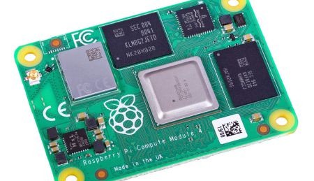
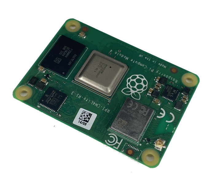
Figure 1 and Figure 2 will give you a first impression of the PCB.
The Compute Module 4 comes now in 32 varieties. You can select wireless or no wireless, onboard EMMC with 8, 16 or 32 GB or no onboard EMMC and 1, 2 ,4 and 8 GB of RAM. This means you can select the version that’s just right for you. Refer to the Specifications text box for the specs, which are the same as those for the Raspberry Pi 4.
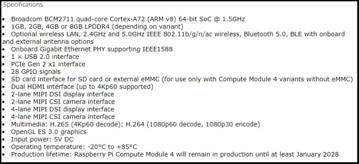
Figure 3 shows the component sections found in a Compute Module 4 with wireless and without EMMC installed.
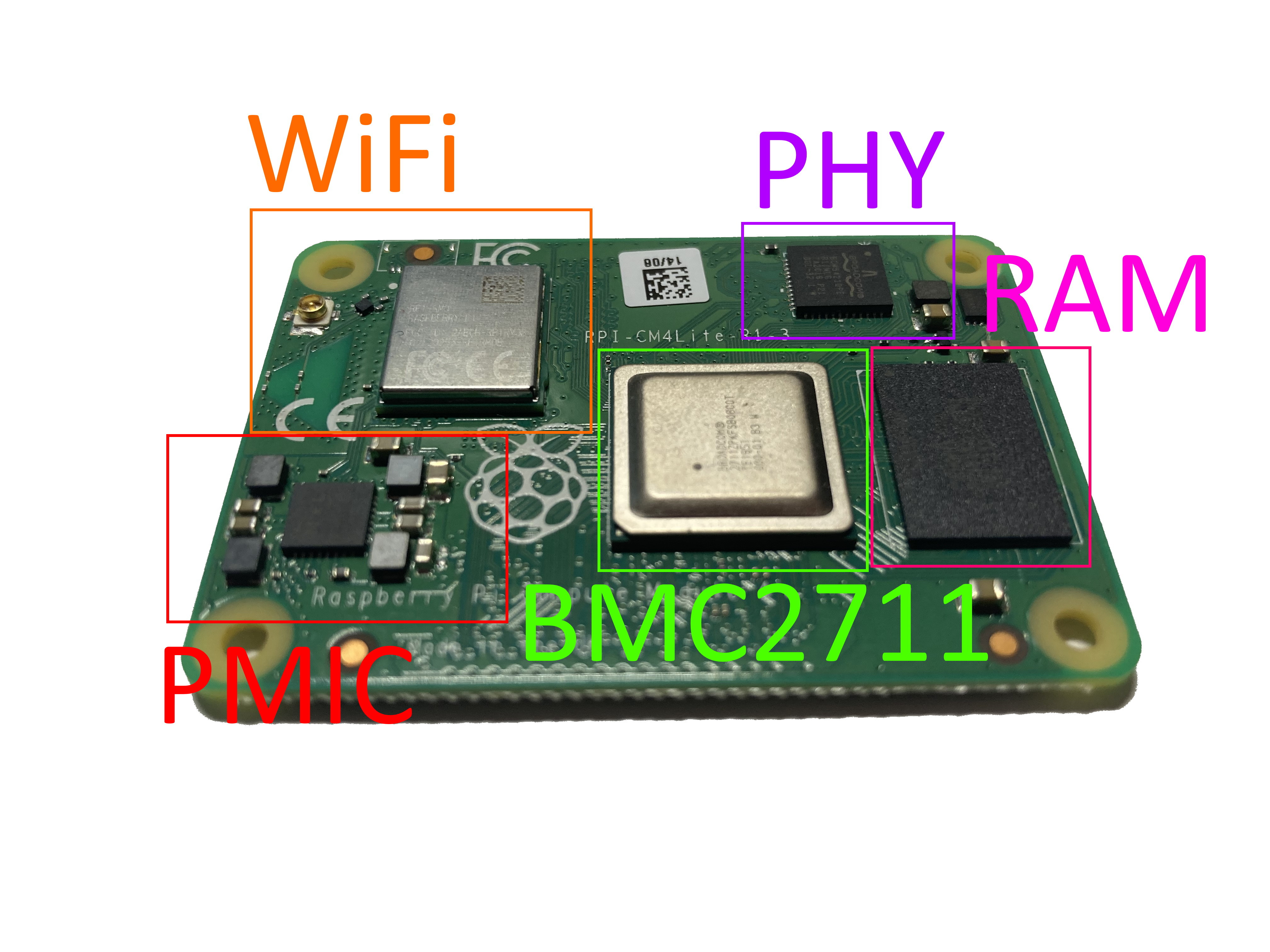
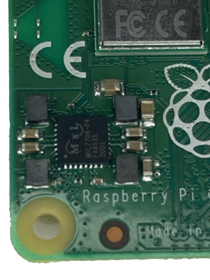
On the left is the PMIC responsible for all the power rails that are needed by the Compute Module 4 to operate (Figure 4).
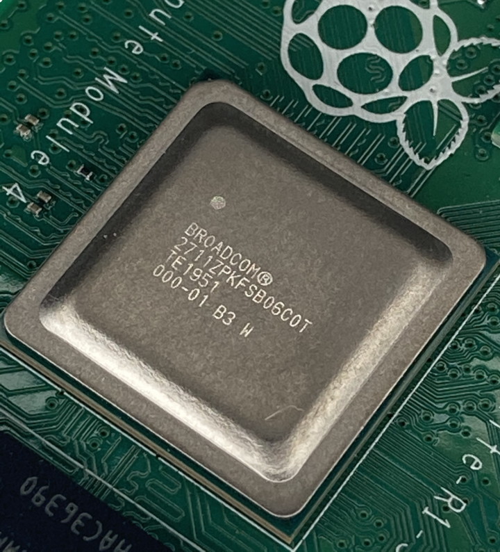
Located next to it is the wireless module supporting Wi-Fi with 5GHz and 2.4GHz and also offering Bluetooth connectivity. In the center (Figure 5), you find the BCM2711, the SoC that is the heart of the Compute Module 4 and offers four Cortex-A72 cores.
At the top right (Figure 6), a BCM54210PE will provide 1000Base-T Ethernet support, including IEEE1588-2008 support for precision timing.
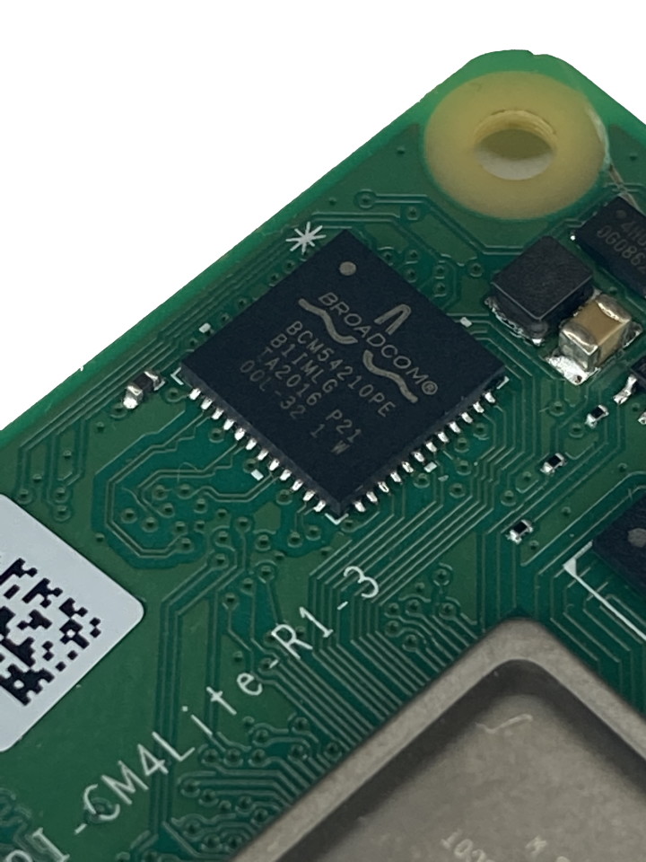
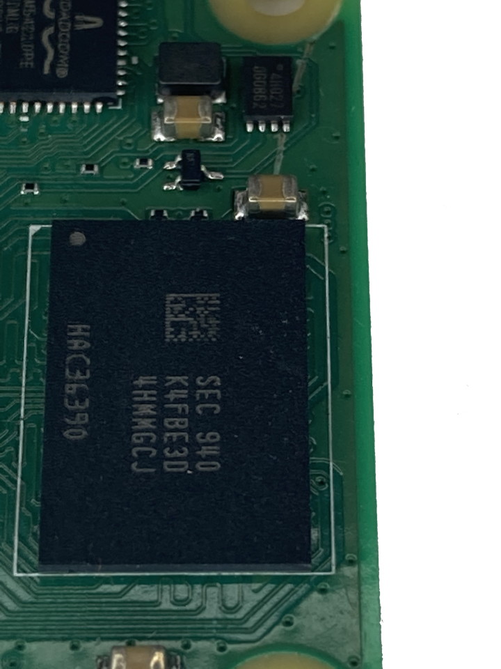
This means all you need to do for your one base board to get Ethernet support is just attaching a MagJack, and for good practice, also add some ESD protection. On the right side (Figure 7), we have a RAM module and on top a small flash chip with basic boot information on it.
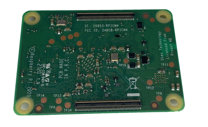
On the bottom (Figure 2), you can see capacitors and oscillators as required support for the SoC. You can also see two 100-pin Hirose connectors used to attach the Compute Module 4 to a baseboard. This is a change from the former Compute Module. One side of the connector has all the power and low-speed signals attached to it; the other one carries all the high-speed signals, making routing less of a hassle. For power we only need to supply 5 V to the module; the onboard DC/DC converter will generate all the voltages required for the Compute Module 4.
Refer again to the Specifications text box. The USB 3.0 interface on the Raspberry Pi 4B is not listed, and there is a good reason for that. With the Raspberry Pi 4B, there was a USB 3.0 controller attached to the BCM2711 via a PCI Express 2.0 single lane connection. This circuitry is not included on the Compute Module 4 and exposes the PCI Express lane for our own use. This creates new possibilities to utilize a Raspberry Pi where the former ones could not work. In the next section, I’ll explain how to get started with the module and how to develop your own creations.
Raspberry Pi Compute Module 4 I/O Board
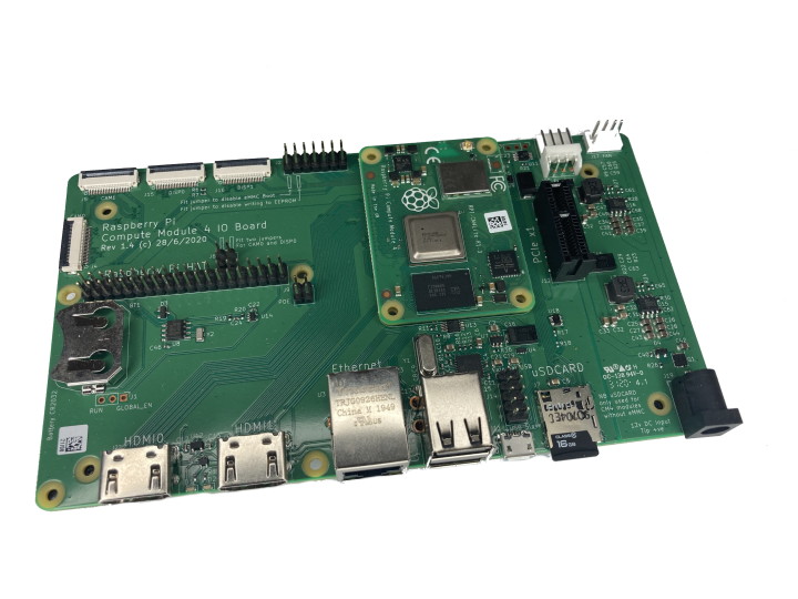
To get started with the Raspberry Pi 4 Compute Module, the Raspberry Pi Foundation also created an I/O Board (Figure 8) that exposes all the nice features of the Compute Module and also includes PCI Express 1x slot with it.
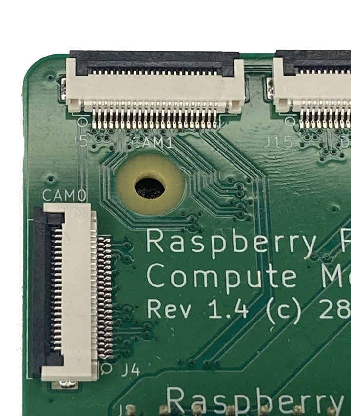
The board offers more connectivity than you get with the other Raspberry Pi 4 products, two camera inputs (CSI-2 interface with two or four channels, shown in Figure 9).
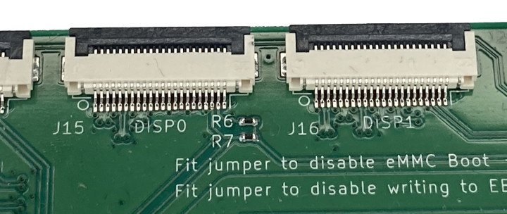
Two display connectors (DSI with two or four channels, shown in Figure 10) enable multiple monitors and vision-processing capabilities.
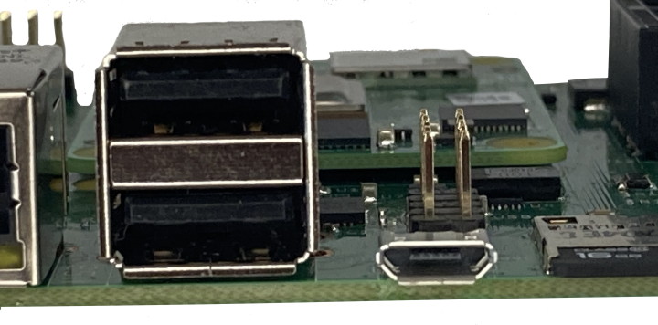
Want to attach a mouse and keyboard? The internal USB 2.0 port of the CM4 has been added with an USB 2.0 Hub on the I/O Board providing up to four USB 2.0 ports (Figure 11).
The I/O Board also includes an RTC Module that can be used as a watchdog or to boot the system in given intervals.
For the power input, all you need on the board is a 12 V supply (if you are using PCI Express cards). If you are not using the PCI Express slot, input voltage can be up to 26 V. Something that has changed and is welcome are the two regular size HDMI ports that can be found on the I/O Board to use the common HDMI cables (Figure 12).
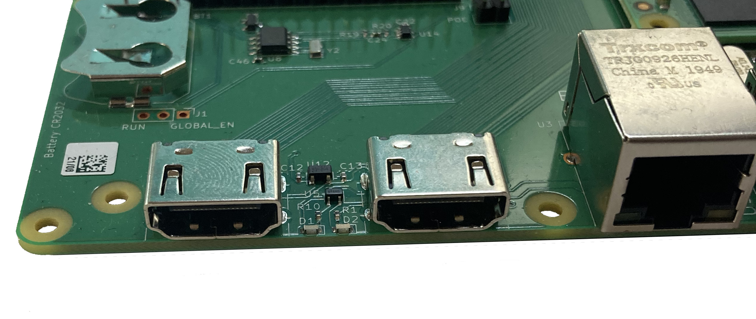
Finally, you get a LAN port and also a nice microSD Card slot. What makes the I/O Board interesting are the KiCad project files that the publicly released and allow for a fast start if you are using KiCad. The Compute Module 4 is added here as component and can be easy added to your own boards and design without fiddling to create a component in KiCad (Figure 13).
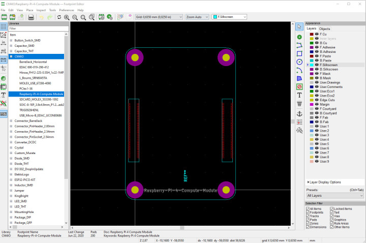
Only a 3D model is not included.
Putting the parts together
If you plan to develop with the Raspberry Pi Compute Module 4, the I/O Board is a desirable companion as it exposes all interfaces in a nice usable manner and gives also access for PCI Express devices. Getting started is as easy as with an ordinary Raspberry Pi 4: write an image to a SD Card and boot it up. If a mouse and keyboard are connected to the USB ports, they will not show up or work as used on the Raspberry Pi 4. If you want to use the USB ports with peripherals, you need to add a line inside the config.txt, which can found inside the BOOT partition of the SD Card. Add dtoverlay=dwc2,dr_mode=host at the end of config.txt, to get next time you boot the USB ports enabled. With the mounted PCI Express 1x slot adding cards that are 1x slot (one PCI Express lane) compatible is not a problem, but you have to keep in mind that those cards are powered from the 12 V input, so ensure enough power can be supplied. PCI Express has a nice part in the spec that allows cards that are designed for slots with 4x, 8x or 16x configuration to also work with less lanes — meaning, they should work in 1x slots. Due to mechanical constrains, we cannot plug such a card directly into the Raspberry Pi I/O Board.
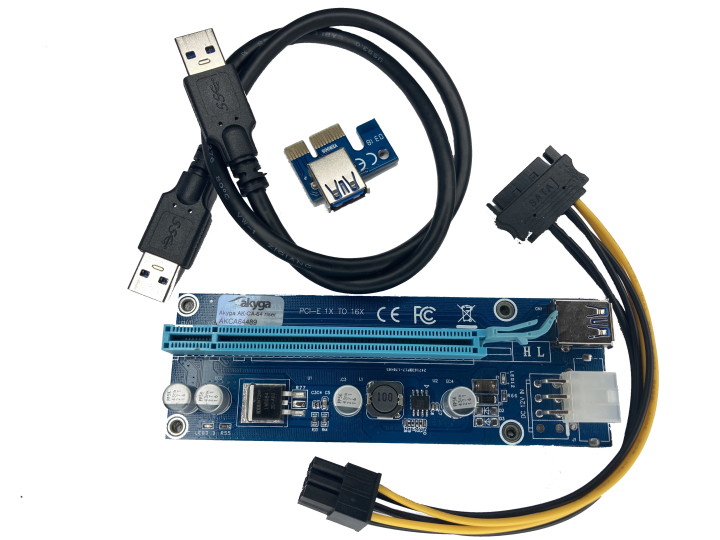
Thankfully, during the increase in GPU-based crypto mining, this problem has also arisen on modern PC systems and solutions were developed. A suitable adapter board with its own power supply can be purchased for less than 10 bucks (Figure 14) and attached to the I/O Board.
After the Raspberry Pi Compute Module 4 is booted and Linux runs, with lspci a short look on the detected PCI Express cards is possible. As you can see in Figure 15, an Intel dual port network card is attached.
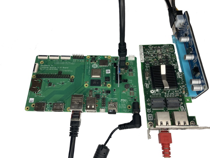
This one is known to have a working Linux driver in mainline and should add additional network ports to the Raspberry Pi Compute Module 4. The output of lspci looks promising, the card is recognized, but there is no driver loaded. The reason for that is quite simple: the stock Kernel that ships with the Raspberry Pi OS has only drivers built in that are required for the day-to-day usage.
Are you wondering if connecting a GPU would work with this method? Connection is possible, but it will not work as you can see in this video. For an Ethernet controller and other PCI Express devices like SATA cards, to get them to work you need to recompile the Kernel for the Raspberry Pi 4. As this is a software issue, it can be solved; but it is out of scope at this time to build a new kernel for the basic driver. Software, kernel builds, and driver are a separate topic that will be addressed in the future. Also, some PCI Express devices do not play at all with the Raspberry Pi Compute Module 4 as the driver assumes something that only can be found in X86/AMD64 world, like is currently the case with the GPU driver.
Ready to start innovating?
The Compute Module now comes in a new form factor and makes a first board design easy. Provided with KiCad symbols and schematics for the I/O Board, it simplifies product development. Why not fit a Raspberry Pi Compute Module 4 inside a set top box or home-built handheld? With the exposed PCI Express lane, we can add quad port Ethernet cards to provide in sum five ports at gigabit speed. That sounds like the ingredients for a Raspberry Pi Compute Module 4-based router.
Given the price point for the Raspberry Pi Compute Module 4 and the I/O Board, starting is not too expensive, as the components are reasonably priced. If you want to build around the Raspberry Pi, it is easier than ever with the current generation of Compute Modules.
(200590-01)
Want more great Elektor content like this?
Take out an Elektor membership today and never miss an article, project, or tutorial.
Discussion (0 comments)