
Review: Nimbus 3D Time-of-Flight Camera
on
Due to its comparatively low hardware cost and relatively simple control, Kinect is still very popular in the field of robotics, even though Microsoft abandoned the technology long ago. Pieye's time-of-flight (ToF) camera module, named Nimbus 3D, is designed to turn a Raspberry Pi into a depth camera. As the author of a Kinect book I could not resist a little experimentation. Before we begin, it may be of help to review the document under [1] where you can find a comparison of various depth sensor systems from the Kinect series.
Nimbus 3D Hardware
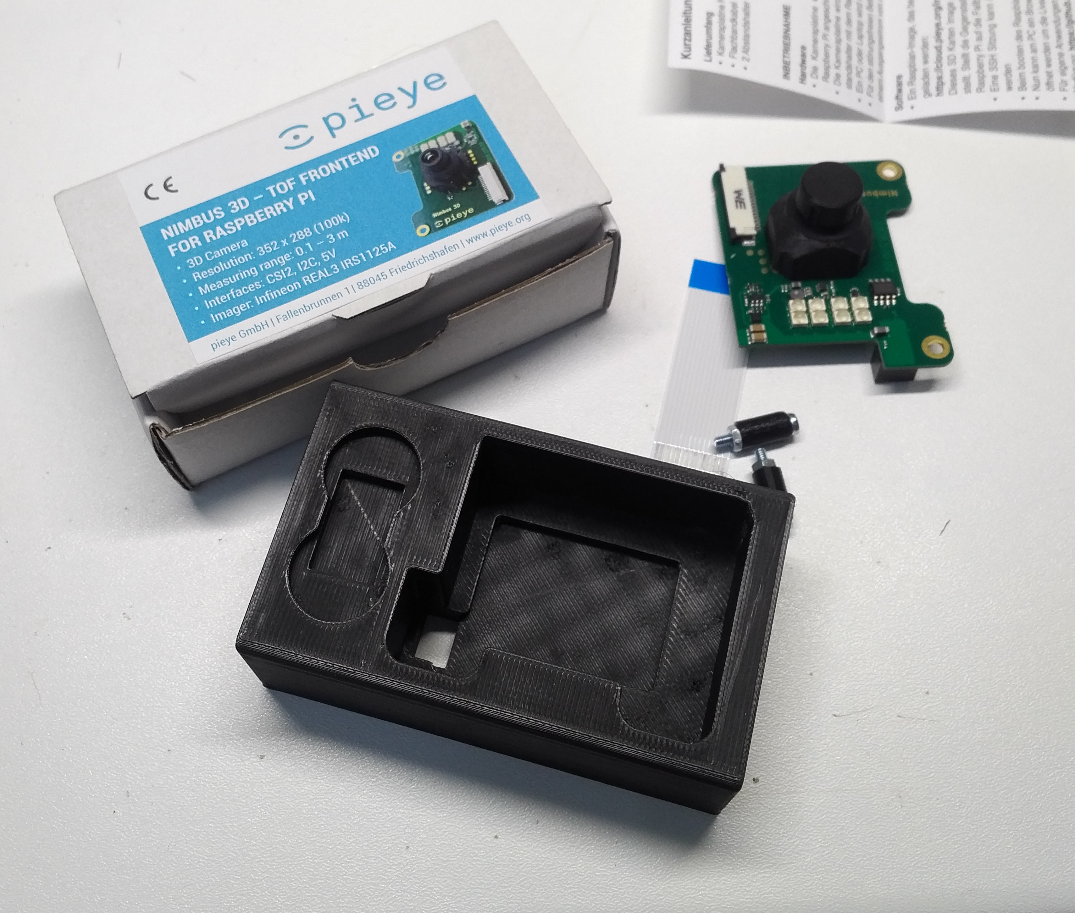
Elektor supplied the camera in a comparatively compact package that includes the circuit board, a ribbon cable and two screws, as well as the 3D-printed spacer shown in Figure 1.
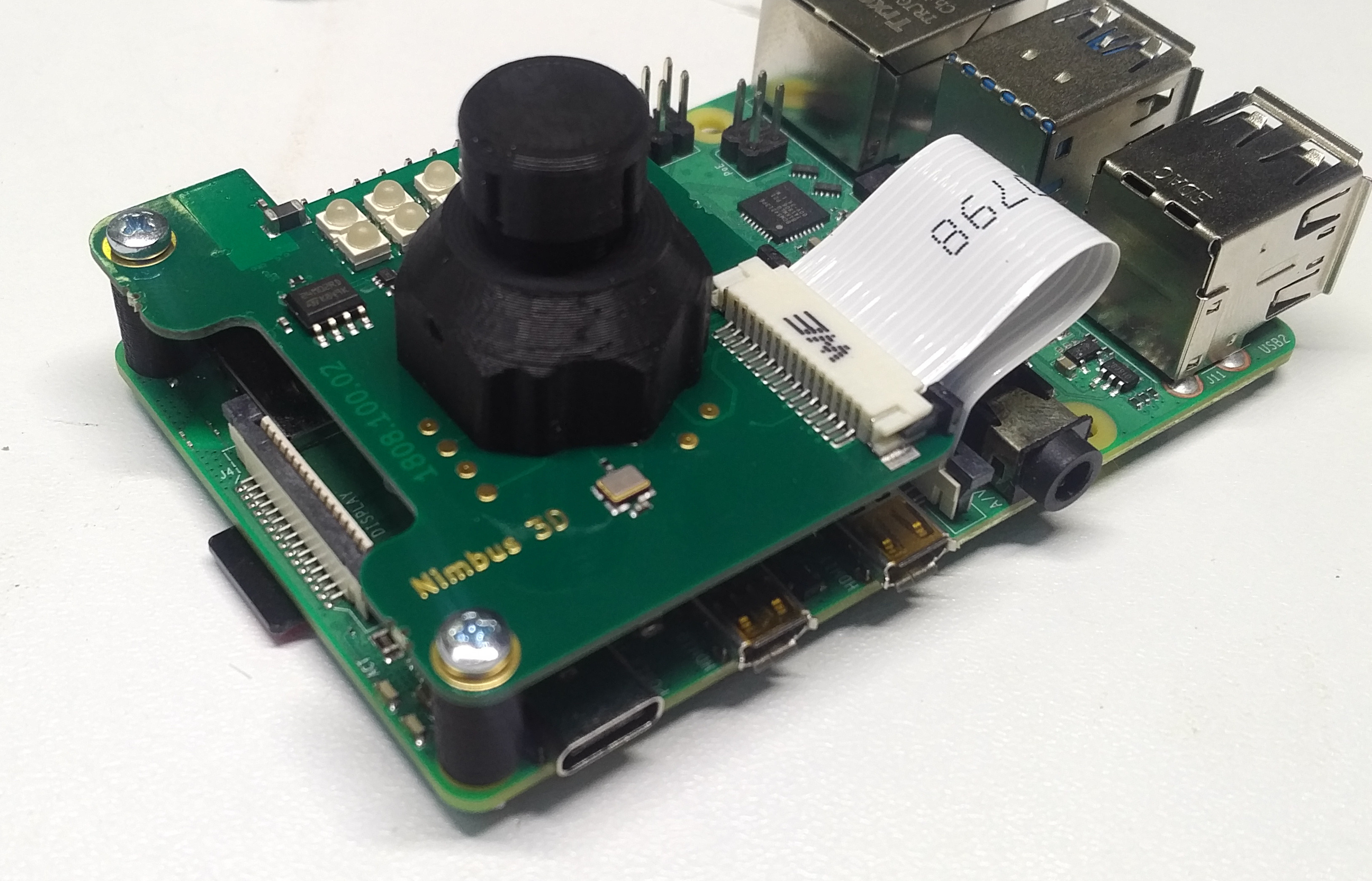
Because of the large amount of data to be transmitted by the sensor used, communication between the board and the single-board computer takes place via the camera port. For this purpose, before actually connecting the board, make sure to connect the camera connector of the RPi with the ribbon cable. Then connect the board to the GPIO port, install the screws (a little crooked) and enjoy the result as shown in Figure 2.
When testing with a Raspberry Pi 4 there was about a half-a-millimetre gap after connecting the GPIO headers and inserting the screws. This was linked to the black (and also 3D-printed) spacers that proved to be a bit too long. This problem can be solved using a file or a handheld electrical grinding tool (Proxxon/Dremel).
Initial operation
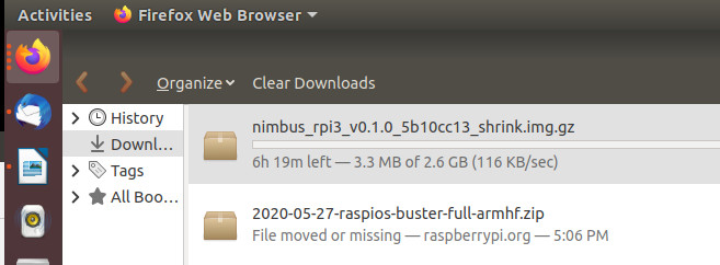
Fast hardware in conjunction with Unix computers have always had the unpleasant characteristic that, for end users, they are often only accessible through kernel modules and other difficult-to-configure interfaces. In the case of Nimbus 3D it is simpler because the required code is provided with as a finished image file at [2]. A few days before the editorial deadline, the manufacturer provided an update that included support for Raspberry Pi 4 and a GitHub repository. If you download your image from [3], you can download a little faster — the Nextcloud service is sometimes a bit sluggish (Figure 3).
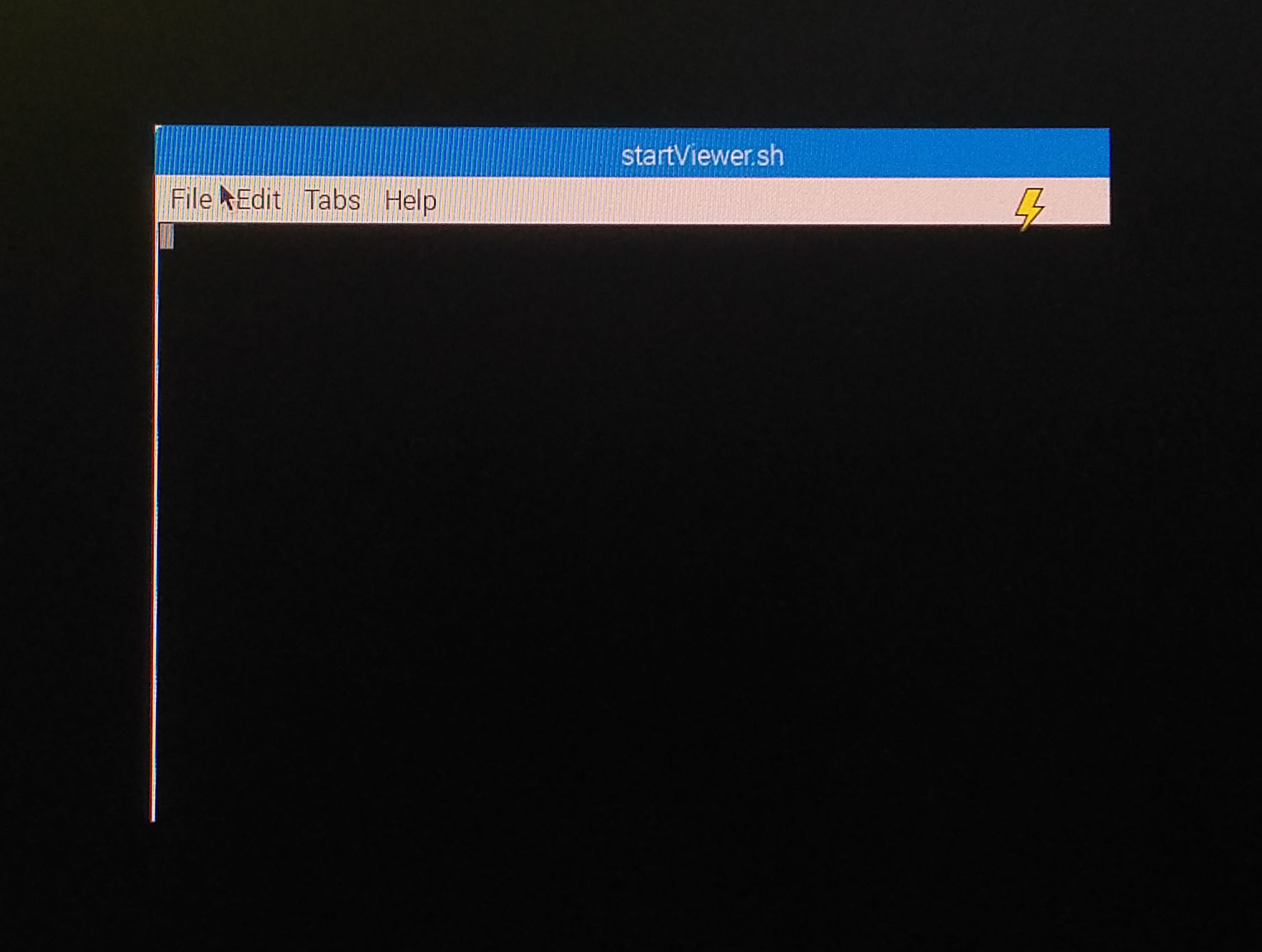
A test of the image nimbus_rpi3_rpi4_v0.1.78_d998e541_shrink.img.gz on an SD card using a Raspberry Pi 4 worked in a dry run after the update. But the remaining tests discussed here were made with a Raspberry Pi 3B+. The system rebooted once and then presented a terminal window (see Figure 4).
For the actual start-up, an Internet connection is required in addition to a monitor connected via HDMI to check the status of the output. Nimbus 3D is not a stand-alone system. Instead it is intended that the Raspberry Pi — as with a Kinect — operates as a camera that transmits the information it captures to a workstation. Due to the high frame rate, a Gbit Ethernet connection results in less latency here. An extremely powerful power supply unit is required and use of the official power supply unit or a genuine equivalent prevents problems.
This means that the next task is to determine the IP address of the Raspberry Pi and then open the associated web page in the browser of another PC. If you use Ubuntu, like I do, and have both the Raspberry Pi and the PC on the same network, you can use NMAP to search for it as shown in this approach:
tamhan@TAMHAN18:~$ nmap -sP 192.168.1.0/24
Starting Nmap 7.60 ( https://nmap.org ) at 2020-08-11 06:06 CEST
Nmap scan report for sagemcom (192.168.1.1)
Host is up (0.00055s latency).
Nmap scan report for raspberrypi (192.168.1.66)
Host is up (0.0015s latency).
Nmap scan report for TAMHAN18 (192.168.1.68)
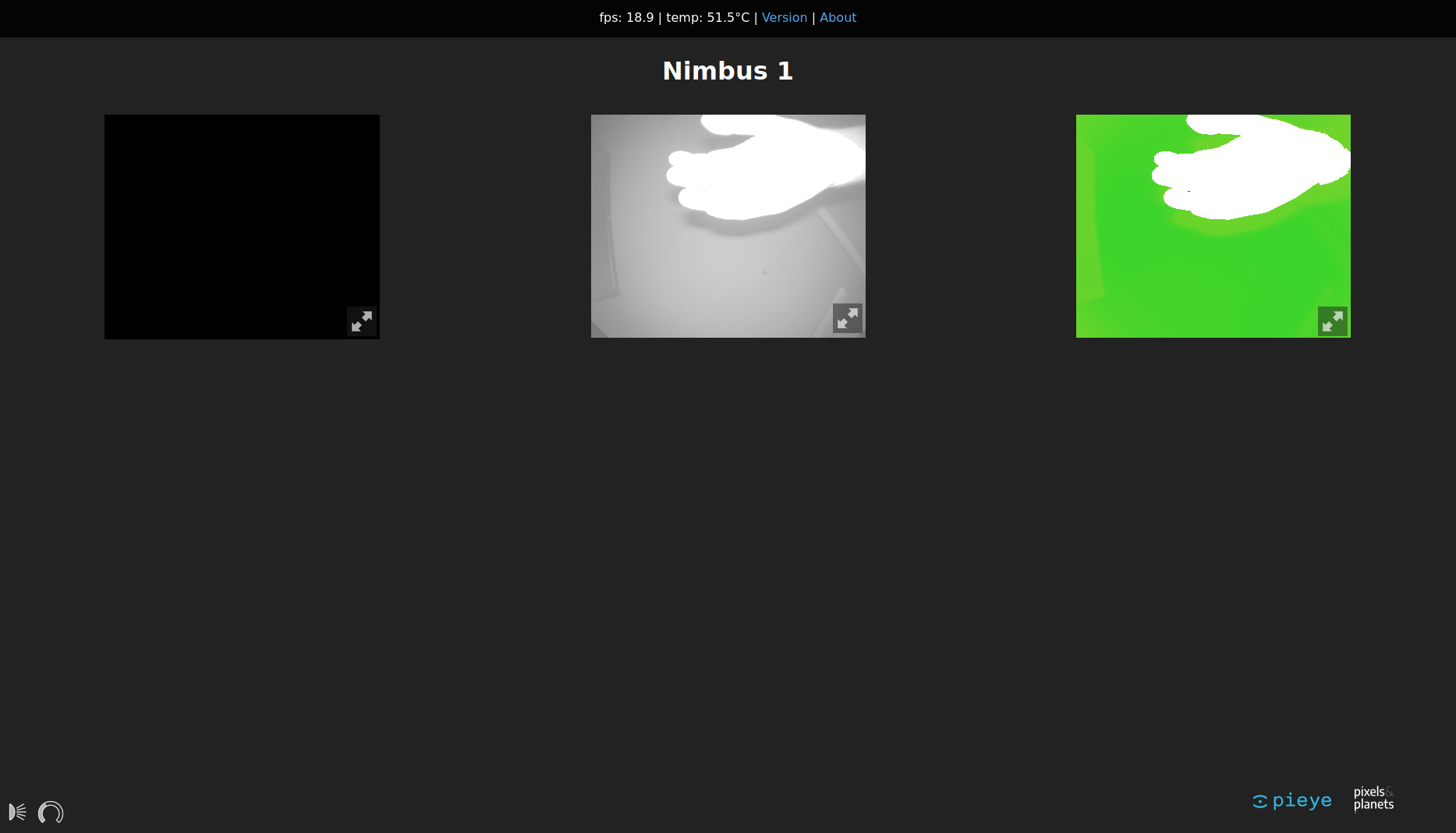
By the way, the command used here is only valid if the router issues IP addresses to the network client using the 192.168.1.x base address. If the base address is different, you must adjust the entries accordingly. If the connection is successful, the web page appears as in Figure 5. You can see my hand, as well as the cable ducts on the ceiling, and even the gas pipe relatively well. This is not really surprising since the datasheet promises a resolution of 352 × 288 pixels with a measuring range of 0.1–3 m.
Experience shows that depth sensors have more problems at close range. Since I had just opened a Tektronix 577, Figures 6 and 7 show two images of it.
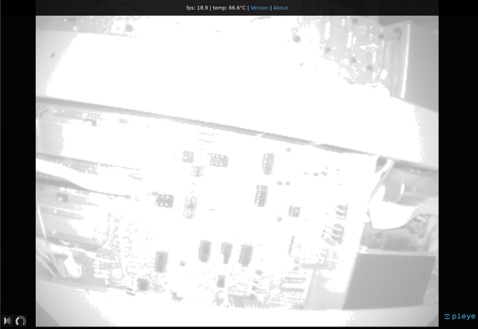
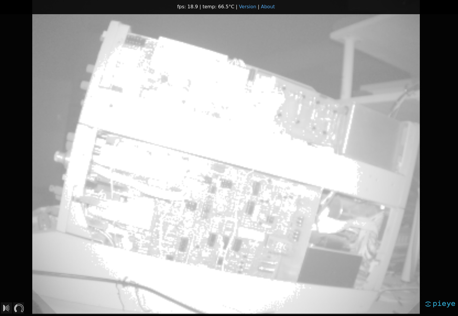
What is most noticeable is that the LEDs used for illumination lead to overexposure at a certain minimum distance.
Two things are important here. First, the LEDs on the board only light up red very weakly because they are infrared LEDs. To check that they are functioning, a smartphone camera is a suitable tool. My BlackBerry had no problem proving that the LEDs were operational. Furthermore, the comparatively high thermal output generated has to be taken into account. The room temperature in my temperate underground bunker was 20°C. Although the Raspberry Pi was completely open on the table, it still reached temperatures of up to 70°C. The use of a Raspberry Pi in an enclosure without some form of cooling is, therefore, not recommended.
The display of depth information in the browser may be an interesting capability, but whether this justifies the price of almost €230 is the question. Fortunately, there is a Python library under [4] that allows developers to integrate the depth information into your own applications. Interestingly, the provider relies on web sockets to implement communication - a procedure that requires Python 3 version 3.6 or later. I have used Ubuntu 18.04 LTS for the following steps with Python version 3.6.9 installed on my PC.
In the next step the package manager PIP, included in Python, is used. Make sure to use PIP3 and not the PIP version included in Python 2.X by mistake.
tamhan@TAMHAN18:~$ pip3 install nimbus-python
. . .
Successfully installed certifi-2020.6.20 chardet-3.0.4 idna-2.10 nimbus-python-0.0.4 numpy-1.19.1 requests-2.24.0 urllib3-1.25.10 websockets-8.1
For a simple first attempt at programming, a test program such as this is suitable:
from nimbusPython import NimbusClient
cli = NimbusClient.NimbusClient("192.168.1.66")
header, (ampl, radial, x, y, z, conf) = cli.getImage(invalidAsNan=True)
After importing the Nimbus library, a client object is created that encapsulates the connection to the Raspberry Pi serving as a camera. Afterwards, the method getImage is called that returns a group of vectors with the depth data. These can then be processed as desired. I would use MatPlotLib for this. This program and the rest of the Python library worked quite well in my tests. Sometimes it was not possible to establish a connection and thus I had to kill the process.
Digression: The development environment
Even though the manual strongly recommends the use of the provided firmeware image, I wanted to do my own experiments. For this purpose I decided to use a Raspberry Pi 4 that was equipped with the firmware image 2020-08-20-raspios-buster-armhf-full.img. The next step was to update the low-level working environment by entering the following commands:
pi@raspberrypi:~ $ sudo apt-get update
pi@raspberrypi:~ $ sudo apt-get upgrade
pi@raspberrypi:~ $ sudo rpi-update
Now I had to add the package source folder. To do this I added the command deb http://apt.pieye.org/debian/ nimbus-stable main to the file /etc/apt/sources.list with superuser rights, then executed the following command to add an SSH key:
wget -O - -q http://apt.pieye.org/apt.pieye.org.gpg.key | sudo apt-key add -
sudo apt-get update
After the obligatory reboot, the following DTOverlay declaration is then added to the end of the file /boot/config.txt, again with superuser rights:
[all]
#dtoverlay=vc4-fkms-v3d
dtoverlay=irs1125
Now the server responsible for delivering the depth images could be installed — make sure to also enable the I2C bus in raspi-config (sudo raspi-config -> 5 Interfacing Options -> P5 I2C):
pi@raspberrypi:~ $ sudo apt-get install nimbus-server
After that a reboot is necessary again. The following commands download the web interface and install the Unix server services necessary for its processing:
pi@raspberrypi:~ $ sudo systemctl start nimbusServer.service
pi@raspberrypi:~ $ sudo apt-get install nginx git
pi@raspberrypi:~ $ git clone https://github.com/pieye/nimbus-web.git
Finally, I had to edit the file /etc/nginx/sites-available/default and make the root declaration point to the software downloaded from GitHub as follows:
root /home/pi/nimbus-web;
Now all that was missing was the entry of sudo service nginx restart that restarted the web server and made the web interface accessible at the IP address of the Raspberry Pi. I called this up via my PC and was presented with three black screens. An analysis of the status of the service showed that, shortly after the call, the service had died, leaving me with the black screen shown in Figure 8.
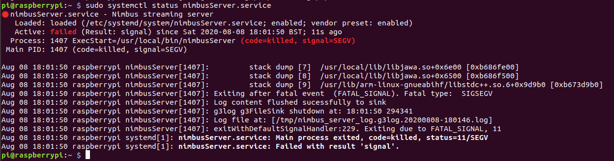
This error is due to an incompatibility between kernel and driver, and is known to the manufacturer and is regularly fixed.
Was it worth it?
There is no question that, with Nimbus 3D, pieye is offering a comparatively inexpensive depth sensor that — even in comparison to the Kinect — delivers quite impressive results. Anyone requiring a compact depth scanner today has little choice in this area. It is clear that there are better sensors for military applications. However, whether one wants to spend so much money on them is rather questionable.
Apart from the undeniable advantages of the product discussed, there are aspects that could be improved. The fact that there are no connections to supply the board directly or via a power supply unit bothered me. Better Python software would also help. In any case I hope that, through this review, I have provided enough to give you a rough idea of what to expect with this sensor.
(200488-02)
Want more great Elektor content like this?
Take out an Elektor membership today and never miss an article, project, or tutorial.
Discussion (0 comments)