The microcontroller
The SAM D20J18 is an interesting member of the ARM Cortex-M0+ family. It offers 64 pins, 256 kB of flash memory, 32 kB of SRAM, and a wide range of peripherals, and can run at a maximum clock frequency of 48 MHz. It is power-efficient and fast, and is therefore suitable for many different applications. Its current draw is only 70 μA/MHz and can run from a supply voltage of between 1.62 V and 3.63 V. Of particular interest are its peripheral touch controller (PTC) and its event system. We will describe the PTC later in this course, and we will show how it can be used in practice. The event system, as in the ATxmega microcontroller series, can be configured for example to wake the CPU from sleep when a peripheral unit such as the ADC triggers an event; however, not all peripherals are supported in this way. The microcontroller has two sleep modes: in idle mode only the CPU is powered down, while in standby mode the clock source and all peripheral units (except those otherwise configured in software) are put to sleep.
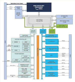
Figure 2 (click image to enlarge)
Figure 2 shows a block diagram of the microcontroller family. On the left is the ‘ARM single-cycle I/O bus’, which allows the processor to have fast access to the GPIOs. Below that is the serial debug interface, which has direct access to the processor core. Below the ‘high speed bus matrix’, which connects the core to the memories on the right via slave ports, you can see several data buses and the peripheral access controller: this is in contrast to the arrangement in conventional eight-bit microcontrollers. The peripheral access controller can prevent peripheral registers from being written to if necessary. The most important peripherals are connected to the APB-C bus: among these the most interesting are the six SERCOM blocks which provide for serial communications using a range of different protocols including USART, I2C and SPI. The pins used by these blocks are configurable. With the exception of the PTC, the remaining peripheral blocks will be familiar from eight-bit microcontroller designs, although the versions here are typically more powerful and present in greater numbers. Each of the eight timer/counters can be used in 2 x 8 bit configuration, 1 x 16 bit, or alternatively two counters can be chained together to form a 32-bit counter. The left-hand side of the block diagram is less exciting, being mainly concerned with power management and clock generation.
We will look in more detail at the possibilities offered by the various peripheral blocks in the next installment in this series, and show step by step how they are configured and used in practice. The data sheet for the device, which runs to some 700 pages, can be downloaded from the here (pdf).
The expansion boards
Atmel has developed several expansion boards for the Xplained Pro board. They are designed to help developers new to the device rapidly get to the point of having a working prototype, and to help them learn about the microcontroller. The expansion boards conveniently plug directly into the headers on the main circuit board. Each expansion board includes an ATSHA204 ‘CryptoAuthentication’ chip, which provides information to the EDBG chip on the Xplained Pro board, for example regarding the allowable supply voltage range and maximum current consumption. This information is then passed on to Atmel Studio, which allows the development environment to offer links to data sheets, libraries and example programs.
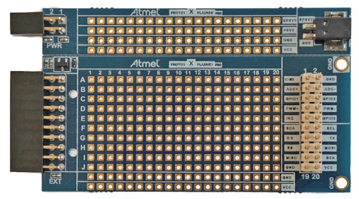
Figure 3: Prototyping board by Atmel with a grid of uncommitted solder pads.
If you want to build your own expansion board and connect it to the Xplained Pro board, the PROTO1 Xplained Pro (Figure 3) provides the answer. It includes a total of 200 solder pads for prototyping and is connected to headers EXT1 and PWR. On the right the same pins are brought out in a different order to provide a connection for an ‘Xplained Top Module’. A groove allows the upper part of the board, which includes the power supply connections, to be broken off if it is not wanted.



Discussion (0 comments)