
Circuit Simulation with TINA Design Suite & TINACloud
on
Editor’s Note: This article is an excerpt from the 440-page book Circuit Simulation with TINA Design Suite & TINACloud (D. Ibrahim, Elektor 2022). The excerpt was reformatted and lightly edited to match Elektor's online article style. Being an extract from a larger publication, some terms in this article may refer to discussions elsewhere in the book. The author and editor have done their best to preclude such instances and are happy to help with queries. Do you have any technical questions or comments related to this article? Email the author or Elektor.
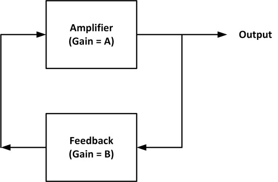
A sinusoidal oscillator consists of an amplifier and a feedback network (Figure 1). The following two conditions must be satisfied to have a working oscillator:
- the loop gain (A × B) in Figure 1 must be greater than or equal to unity;
- the total phase shift around the circuit must be 0 or 360°.
Some simulations of operational amplifier-based oscillator circuits are given in this section.
Simulation 1 — Phase-shift Oscillator
This is sometimes called the RC oscillator. Each RC pair introduces a 60° phase shift. Three resistors and capacitors are used here to introduce a 180° phase shift to the feedback loop. The total loop phase shift is, therefore, 0° as required for oscillation.
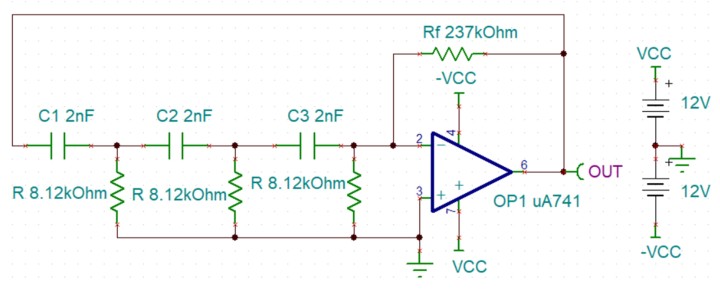
TINA schematic
Figure 2 shows the circuit diagram. The RC network is connected to the inverting input of the operational amplifier.
Assuming the resistors and capacitors are the same, the requirement is that the voltage gain of the amplifier must be greater than or equal to 29, i.e.:
![]()
The frequency of oscillation is given by:
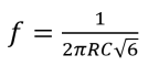
In this example, the required frequency is 4 kHz. Choosing C = 2 nF, we can find the required value of R from:
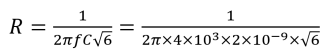
which gives R = 8.12 kΩ. Then,

and we choose Rf = 237 kΩ. A type UA741 operational amplifier is used in this project. The TINA circuit is available as the file sim9 (see article end).
TINA Simulation
The steps to run the simulation are:
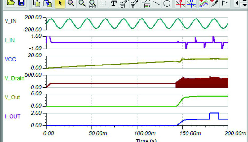
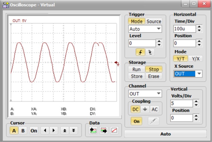
- Click T&M → Oscilloscope and Run. Set the Time/div to 100 u.
- Check the output waveform (Figure 3). The period is 250 µs which corresponds to 4 kHz. Note the glitch in the output waveform on the oscilloscope. The oscilloscope can be synchronized to create a stable picture. To do this, select Normal under Mode and synchronizing signal under Source. It may also be needed to set the (Trigger) Level.
Simulation 2 — The Wien Bridge Oscillator
This is one of the simplest sinusoidal oscillators. The Wien Bridge oscillator is a two-stage RC coupled circuit that has good stability at its resonant frequency, low distortion, and is very easy to tune, thus making it a popular circuit as an audio frequency oscillator.
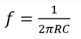
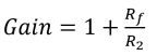
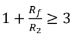
The circuit uses a series RC connected with a parallel RC. The phase shift of the circuit is 0° at the resonant frequency, and the circuit is connected to the positive input of the operational amplifier so that the overall phase shift is 0°. Usually, a non-inverting amplifier configuration is employed. The condition for oscillation is that the voltage gain must be greater than or equal to 3. Assuming the same resistors and capacitors are used, the frequency of oscillation is given by:
In this example, the required frequency is 5 kHz. Choosing C = 3 nF, we can find the required value of R from:
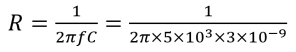
which gives R = 10.6 kΩ.
To satisfy the gain condition, for a non-inverting amplifier (look ahead to Figure 4):
Choosing Rf = 100 kΩ:
Which gives:
and we choose R2 = 47 kΩ.
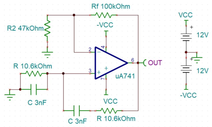
TINA Schematic
Figure 4 shows the circuit diagram. The feedback circuit is connected to the noninverting input of the operational amplifier and the gain is set through Rf and R2. A type UA741 operational amplifier is used in this project. The circuit is available as a file: sim10.
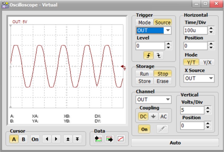
TINA Simulation
The steps to run the simulation are:
- Click T&M → Oscilloscope and click Run. Set the Time/div to 100u.
- Check the output waveform (Figure 5). The period is 200 µs which corresponds to 5 kHz.
Simulation 3 — The Colpitts Oscillator
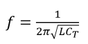
The Colpitts oscillator uses a capacitive voltage divider network as its feedback source. Two capacitors, C1 and C2 are placed across a single common inductor, L, where C1, C2, and L form the tuned tank circuit. The feedback circuit is usually connected to the negative input. C1, C2, and L provide the additional 180° phase shift required to make the total phase shift 0°.
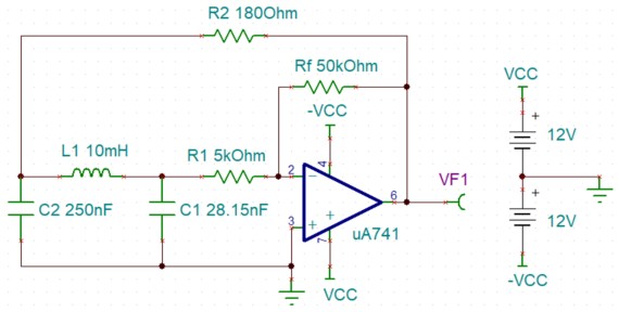
The frequency of oscillation is given by:
Where CT is the series combination of C1 and C2, i.e.:
The amount of feedback depends on the values of C1 and C2. Therefore, by changing the values of these capacitors, we can adjust the amount of feedback voltage returned to the tank circuit. The ratio of C1 to C2 is the feedback ratio, B:
B = C1 / C2
For oscillations, AB ˃= 1, where A is the amplifier gain.
Or, A ˃= C2 / C1.
In this example, the required frequency is 10 kHz. Choosing L = 10 mH we can find the feedback ratio from:
which gives 25.3 nF. Choosing C2 = 250 nF gives C1 = 28.15 nF, which corresponds to a feedback ratio of B = C2 / C1 = 250 / 28.15 = 8.88. We can therefore choose the amplifier gain to be around 10 (see Figure 6), giving:

Choosing R1 = 5 kΩ gives Rf = 50 kΩ.
TINA Schematic
Figure 6 shows the circuit diagram. The feedback circuit is connected to the inverting input of the operational amplifier and the gain is set through Rf and R1. A type UA741 operational amplifier is used in this project. The circuit is available as a file: sim11.
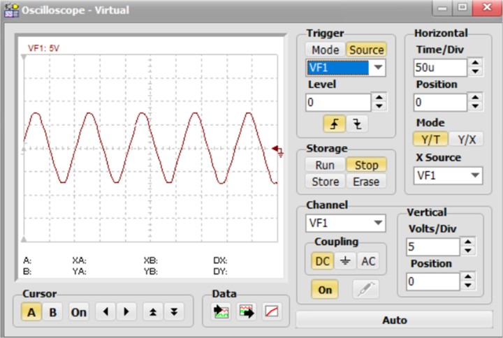
TINA Simulation
The steps to run the simulation are:
- Click T&M → Oscilloscope and Run. Set the Time/div to 50u.
- Check the output waveform (Figure 7). The period is 100 µs (100u) which corresponds to 10 kHz.
Where to Get It?
The TINA simulation files mentioned in this article are contained in the software bundle released by the author and DesignSoft in support of the book. The software is available for free downloading from the book resoources and info page on the Elektor Store website. Scroll down to the Downloads, and click on this file name: Contents_Circuit Simulation with TINA Design Suite & TINACloud. Save the ZIP archive file locally (2.45 MB)) and then extract it. Open your version of TINA and load the files sim9, sim10, sim11 as mentioned in this article. Feel free to modify them for your own applications.
Discussion (8 comments)