
Component Identification
on
Many readers will, like me, be hobbyists who scrounge parts off old electronic equipment. I got interested in electronics in my early teens — about 50 years ago — and my father, who was in sales at an accounting machine firm, got me scrap boards from the techs there. The boards contained transistors, resistors, diodes and a few capacitors. They had the leads bent over on the underside of the board and even the large soldering gun my dad also got for me had problems removing some components. However, this was in Zimbabwe (then Rhodesia), which was not the centre of the electronics universe. Components were expensive and not always easy to get, so these boards were gold for me.
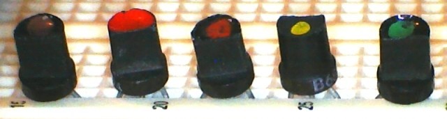
The transistors were in a very weird package, but with a simple transistor tester I built from an article in a magazine, I identified them as NPN types. However, they were marked “B686” and had a dot of paint — brown, red, orange, yellow or green — in a dent on top of the case. Now, in those days, the Internet didn’t exist, and data books were rare and expensive. I did know that transistors marked “Bxxx” were often from the Japanese 2SB series, but when I referred to my copy of the venerable Towers International Transistor Selector book, the 2SB686 was a PNP power transistor and mine were NPN signal types. So, identifying the actual type number of these transistors was a challenge. And not an easy one!
Success came when by chance I saw a table of transistor data in the Practical Electronics magazine I got at the time. There was the 2N2926, with the same case, with a note that the dot of paint on top of the case showed the gain range. The 2N2926 (Figure 1) is a strange-looking transistor, and it had to be the same, even though mine were not marked as such. I confirmed that the gains of my transistors corresponded to those shown in the table, and that sealed the deal. The 2N2926 with its dot of paint is such an unusual transistor that it had to be that, even with a different marking
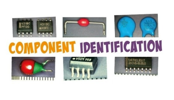
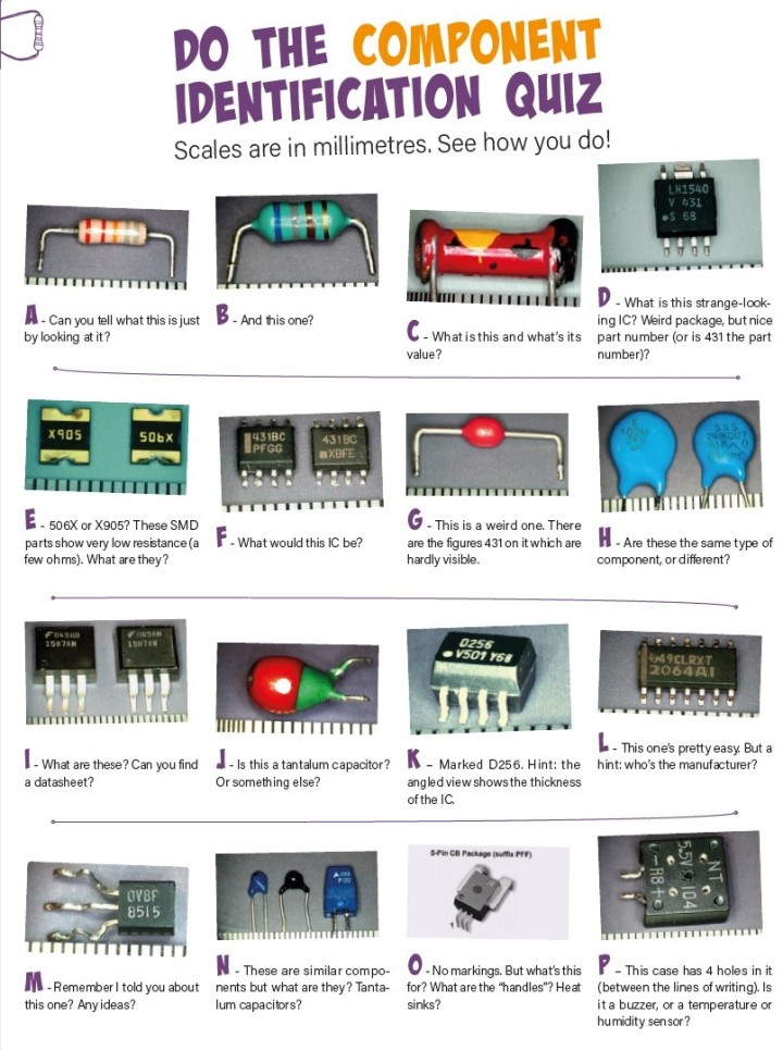
I’ve worked in electronics and telecoms most of my life, and still strip old boards for parts – professional equipment often yields high quality components. Since my (misspent?) youth, I’ve had a lot of challenges to identify even weirder scrounged components, not always successful. But I am passing on here a few of the techniques I have depended on over the years. And I have included a component identification quiz for you to test your own skills. This has a real mix of component types from very old ones to newer SMD types, and I’ve included examples of the problems and techniques I describe here.
Collect Component Data
When I started, data books were difficult to find, and worth their weight in gold. Not as important now with the Internet at hand, but if you see any useful information — colour codes, manufacturers’ information, datasheets, etc. — keep it filed away in your favourites or as a printed copy. I still have the table of transistor data from all those years ago.
These days, get to know your way round the Internet. There are plenty of good datasheet sites out there. Google is your friend! But help Google to help you. If you’re looking for a datasheet, put “datasheet” in the search box. And use the minimum part number you can. I had some ICs recently labelled “2026-1SM,” which, as I had several, I had determined was probably the part number. But I put “2026 datasheet” into the search engine and right away came up with the datasheet for the MIC2026 by Micrel (now part of Microchip) — a dual-channel power distribution switch.
Some datasheet sites take your part number and specify datasheets that are either an exact match, start with or just contain the data you put in — this can be useful to narrow down your search. I save most datasheets to my hard drive — you never know when you’re going to have to hunt for them again — but this is a personal preference. I’ve given a link to my most used datasheet site at the end, and keep a few sites in my favourites, along with some manufacturers’ sites.
How to Read Datasheets
Most datasheets start off with a description of the part, then the absolute maximum ratings. Then follows the nitty-gritty of how to use it, pinouts, etc. The package information is usually at the end, and you often need to look at that to make sure that what you’ve got is indeed what that datasheet is about — the same number of pins and the same package.
Manufacturers don’t all make the same devices in the same package, so you may have to hunt around. Usually, but not always, a part made by one manufacturer will have the same specs as the same part made by another manufacturer, so if you can, find a datasheet from the manufacturer of your component.
Know Your Components
Some components look a lot like something else. These days I can look at a component that looks like a resistor and say “That’s a capacitor” or “That’s an inductor” with a fair degree of accuracy, based on the shape and the colour of the component.
Most people know that something marked “2Nxxxx” is a transistor, and an IC-looking thing with four or six pins is probably an opto-isolator. And I know that a transistor-looking component marked xxNyy (e.g., “35N60”) or one marked IRFxxx (e.g., “IRF540”) is a FET. This comes with experience.
Just while researching this article, I came to the realization that a “V” on an IC often means it’s made by Vishay, which I’ll remember as it may save me some time in future.
How to Test Components
About the time I encountered those 2N2926s, I built myself a simple transistor tester with an old meter, a switch, a 500-kΩ pot and a 1.5-V battery. I still have it today, but nowadays most digital multimeters have a transistor tester built in, and some can test capacitors as well. FETs are a little more difficult but are possible to test in the average home lab. I have a basic LCR meter, which I use a lot, though I’d like a better one.
If you can identify a component as a transistor, FET, capacitor, etc. you are halfway there, and you may be able to use it even without further identification. Some SMT (Surface Mount Technology) components — capacitors in particular — have no markings at all so you need to measure them to be able to use them. A tweezer probe for your meter can make it a lot easier to test SMD parts, and the Elektor Store has a very tasty digital tweezer tester that measures just about anything.
ICs, of course, need specialized testers, but you can make yourself an op-amp tester and you can buy logic IC testers if you get and use lots of logic ICs. A part number and datasheet are first prize for ICs and transistors, but lots of components, particularly passive ones, are usable if you just know their value. Testing components is a subject in itself.
Make the Best Use of Component Print
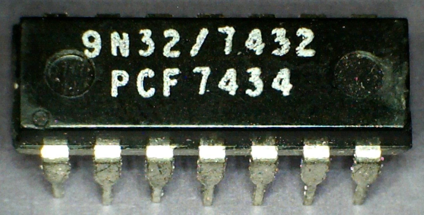
There are usually a few numbers on a transistor or IC and it’s worth a bit of effort to identify which is the type number. Prefixes are often omitted on small SMDs. Get to know manufacturers’ logos. Going straight to the manufacturer’s website can save you lots of time. Most components have a date code which used to be year and week (like 8634) but these days they can be cryptic batch codes. (In the old days, a TTL 74-series logic IC made in 1974, with a 74xx date code (Figure 2) could be a puzzler!)
If you have a few components of one type, look for a code that’s the same on all of them — that will be the part number, the other codes will be date — or batch codes of no interest.
Values on passive components are either shown directly (like 47 pF) or as figures or resistor colour code in the form Digit1, Digit2, Multiplier (being the number of zeros) on the component. So SMD inductors often have the value marked in microhenries in this fashion, so 3R3 is 3.3 µH and 333 is 33 mH (33,000 µH). Capacitors may be marked in picofarads. A tantalum capacitor labelled 227 is 22 × 107 pF = 220 µF. Some components may have five or six rings of colour code, but the Internet is a great help in decoding these.
Most small SMD capacitors are not marked at all, so use your component test skills and equipment to verify them. And get a magnifying glass or a USB microscope (which is what I used to take most of the photos for this article) – it makes it much easier to see the tiny writing on small components.
The internet has many resources to assist you – search for “IC Manufacturers logos” or “SMD codes” if you need more information. And look up “EIA-96” to decode SMD resistors with what looks like a weird 2-number plus 1-letter code.
Consider the Context
If you’re stripping parts off boards, or otherwise know where the component came from, that may give you a clue as to what the part is. A power supply is likely to have a switched-mode PWM IC, whereas an audio board is more likely to have op-amps.
Don’t Expect to Identify Everything!
I have a bag of transistors labelled 0V8F which have stubbornly refused to be identified. SMD components can be difficult or impossible to identify, as they often have shortened part numbers on them. Even with the considerable resources on the Internet, they are not easy.
Be Selective
I mentioned the boards I got as a kid, with bent-over component leads. I religiously unsoldered all of them. These days I won’t touch such components unless they are really special; it’s not worth the effort.
Electrolytic capacitors should always be tested, especially large power supply types, and look for domes on the tops — a dead giveaway that they have gone dry or leaky. Older components such as carbon resistors are really not worth keeping, and older electrolytic capacitors will often be much larger, for their ratings, than modern types.
Many modern SMD ICs have very fine pitch leads or are ball-grid array (BGA) types which need specialized equipment to install and remove on boards. So if it’s not something you can see a use for, junk it. If you think it might be something you can use, identify it to be sure before you go to the trouble of unsoldering it.
Being able to identify and use components from old boards can well repay the time you spend doing it. You can get high-quality components and if you store them systematically, you can often avoid having to buy parts for a project. In addition, you can often use these skills when attempting repairs on circuit boards.
Component or Article Questions?
Do you have technical questions or comments about his article? Email the author at stn564@yahoo.com.au or contact Elektor at editor@elektor.com.
Discussion (12 comments)