
ESP32-Based ArtNet to DMX Converter: Upgrade Your Legacy DMX Device
on
The ArtNet protocol has brought the DMX standard to the network. The new ArtNet devices are, of course, backward compatible with the DMX standard, but not vice versa. What to do then, with a legacy DMX device? The interface presented in this article allows you to upgrade it, granting the compatibility with this new standard.
The idea for this project came almost spontaneously, thinking about the backward compatibility of the ArtNet standard. A universe in both the ArtNet and DMX consists of 512 channels, and the values of each vary from 0 to 255. Most of the latest generation of remote-controlled devices (RDMs) used in the entertainment industry are compatible with both protocols, but how to deal with those that still do their job excellently but receive only the DMX signal? The simplest idea is to convert the signal externally from ArtNet to DMX through a wireless, compact, reconfigurable device.
ArtNet to DMX Converter: Hardware
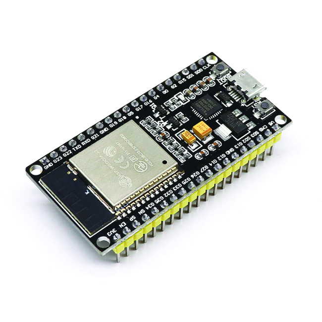
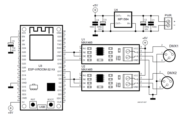
The whole project is built around a 38-pin version of the ESP32 module, shown in Figure 1, while the simple circuit diagram is illustrated in Figure 2. This board was chosen because of its high computing capacity and on-board memory, low cost, small package, and large community. I adopted a 5 V step-down DC-DC converter for the power supply.
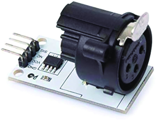
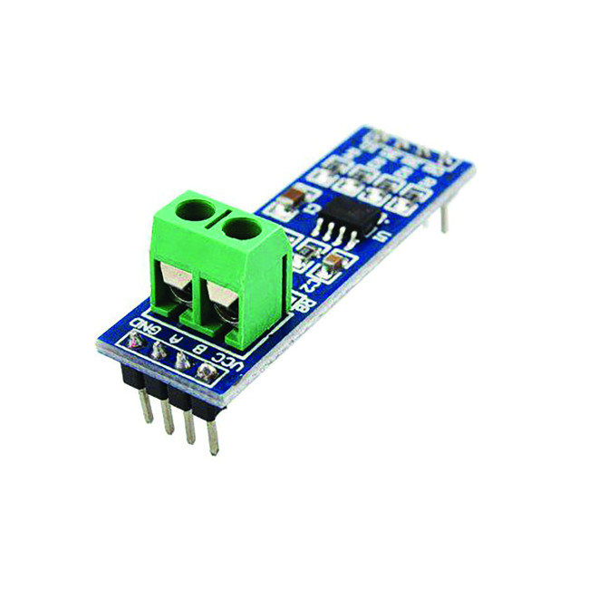
For the DMX section, two TTL-DMX converters, complete with connectors, can be found online (Figure 3), but at a very high cost compared with that of the other components. We therefore decided to use two TTL-to-RS-485 converters (Figure 4) and two female 3-pin XLR panel connectors. Finally, we will need a DC, barrel-type panel connector and a plastic enclosure to close it all up.
Creating Connections: Simplified Circuit Design
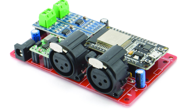
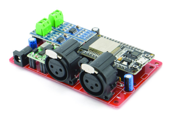
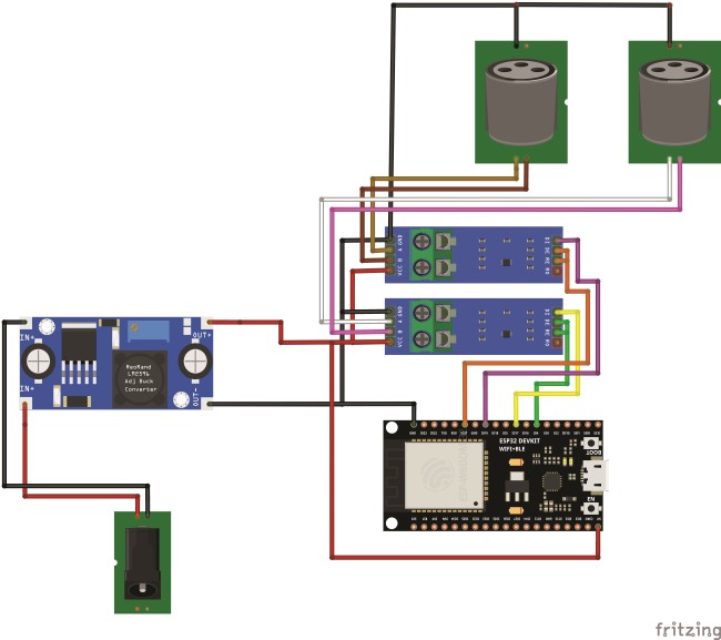
I originally made a PCB for the project, with the 30-pin version of the ESP32 embedded (see Figure 5), but the extreme simplicity of the connections allows for implementation even without a printed circuit board, using the enhanced 38-pin module instead. In fact, the connection diagram is easy to interpret and is available in Figure 6. Let’s start with the power section: The panel-mounted DC plug is connected to the input of the DC-DC converter. The 5 V output of the latter is connected to VIN on the ESP32 (Pin 19) as well as the VCC pins of both RS-485 modules. The same connection should be made for the GND pins of the three boards, which will be connected to the output ground of the DC-DC converter.
As for the signals, each module has three input pins: The RE and DE pins of module A should be connected to IO4 (Pin 26) of the ESP32 module, while the DI pin of the A transceiver should be connected to IO17 (Pin 28) of the ESP32. The output of each transceiver should be connected to an XLR connector according to the following diagram: Pins A and B of the MAX485 should be connected to pins 3 and 2 of the connector, respectively. Pin 1 of the connector can be connected to ground.
Sketch
The sketch for this project is based on the ArtNetWiFiNeopixel GitHub sketch by rstephan and Mitch Weisbord’s DMX_Write. You can download this project’s sketch directly from this project’s GitHub repository.
As always, we will proceed to analyze it as a whole, divided into several listings, and dwell on some highlights of the code. Listing 1 attends to the inclusion of libraries and DHCP configuration. Let’s have a more in-depth look. Several variables that are useful for compiling the sketch are included in the Arduino.h library, along with the inclusion of several other libraries containing basic functionality classes, such as stdlib, stdio, string, etc.
#include <Arduino.h>
#include <esp_dmx.h>
#include "ArtnetWifi.h"
#include <WiFi.h>
#include <ESPmDNS.h>
#include <WiFiUdp.h>
#include <ArduinoOTA.h>
//#define DHCP_DISABLED
#ifdef DHCP_DISABLED
IPAddress local_IP(192, 168, 1, 154);
IPAddress gateway(192, 168, 1, 1);
IPAddress subnet(255, 255, 255, 0);
IPAddress primaryDNS(192, 168, 1, 1); //optional
IPAddress secondaryDNS(1, 1, 1, 1); //optional
#endi
The esp_dmx.h library carries the whole set of instructions to handle sending signals to the TTL-to-RS-485 module.
Then we have the ArtnetWifi.h and WiFi.h libraries for receiving ArtNet packets and managing the connection to the access point, respectively. The ESPmDNS.h, WiFiUdp.h, and ArduinoOTA.h libraries, on the other hand, are functional for OTA firmware loading and setting the device name within the network, using the mDNS protocol.
Then follows a #define DHCP_DISABLED: through this directive we are going to choose whether to set a static IP address or to delegate everything to the DHCP server (commenting out the line). If we decide to use a static IP in the following lines of code, it is necessary to set all related constants to the desired IP, gateway and subnet to which it belongs. You can, furthermore, choose the DNS servers. If we choose to use a dynamic IP, it will still be useful (but not essential) to know the IP address of the ESP32.
Table 1: ESP32 to RS-485-A Module connections.
| ESP32 Pin | MAX485 Pin |
|---|---|
| 4 | DE |
| 17 | DI |
| 4 | RE |
Table 2: ESP32 to RS485-B Module connections
| ESP32 Pin | MAX485 Pin |
|---|---|
| 21 | DE |
| 19 | DI |
| 21 | RE |
We’ll explain more about that later. Listing 2 comprises the remaining part of the preprocessor. The objects related to the WiFiUDP and ArtnetWifi libraries are initially created. Next, in the string constants ssid and password, the name of the Wi-Fi network to which the ESP connects, as well as its password, are defined. The ESP pins to which both RS-485 transceivers will be connected are shown in Table 1 and Table 2.
WiFiUDP UdpSend;
ArtnetWifi artnet;
const char* ssid = "MyArtNetNetwork";
const char* password = "MyArtNetNetwork";
/* First, lets define the hardware pins that we are using with our ESP32. We need to define which pin is transmitting data and which pin is receiving data. DMX circuits also often need to be told when we are transmitting and when we are receiving data. We can do this by defining an enable pin.*/
int transmitPinA = 17;
int receivePinA = 16; //Not connected
int enablePinA = 4;
int transmitPinB = 21;
int receivePinB = 16; //Not connected
int enablePinB = 19;
/* Make sure to double-check that these pins are compatible with your ESP32! Some ESP32s, such as the ESP32-WROVER series, do not allow you to read or write data on pins 16 or 17, so it’s always good to read the manuals.*/
/* Next, let's decide which DMX port to use. The ESP32 has either 2 or 3 ports. Port 0 is typically used to transmit serial data back to your Serial Monitor, so we shouldn’t use that port. Let's use port 1! */
dmx_port_t dmxPortA = 1;
dmx_port_t dmxPortB = 2;
/* Now we want somewhere to store our DMX data. Since a single packet of DMX data can be up to 513 bytes long, we want our array to be at least that long. This library knows that the max DMX packet size is 513, so we can fill in the array size with DMX_PACKET_SIZE. */
byte dataA[DMX_PACKET_SIZE];
byte dataB[DMX_PACKET_SIZE];
//ArtNet settings const int startUniverse = 0;
// CHANGE FOR YOUR SETUP most software this is 1,
//some software send out artnet first universe as 0.
const int maxUniverses = 2;
const int numberOfChannels = 1024;
bool universesReceived[maxUniverses];
bool sendFrame = 1;
int previousDataLength = 0;
For each of the modules, we’ve set the receive pin to 16, although these are not actually connected and of no use in our design. Moving on, the hardware is set with the definition of the ESP TTL ports: We will use ports 1 and 2 for universe A and B, respectively. The data for the 2 DMX universes will be encapsulated in two byte arrays, dataA and dataB, whose sizes are defined in DMX_PACKET_SIZE. DMX_PACKET_SIZE is defined in the esp_dmx.h library and has a value of 513. Finally, all variables used for processing ArtNet packets are defined. We pay special attention to the startUniverse constant: This, in fact, indicates from which universe we want to start considering data.
It should be modified in case we intend to create an installation with multiple receivers from different universes. It may also need to be modified in cases where the program that sends packets has a numbering starting with 1 instead of 0. Constants are then defined regarding the maximum number of universes, channels, and other variables used to monitor states and process loops.
Listing 3 contains all the instructions included within setup(). The serial port is first initialized at 115,200 bits per second to allow debugging of the board, such as to verify the IP obtained. Moving forward, if set, all parameters are configured to obtain a static IP and, if an error occurs, a message is sent out on the serial port. A loop connection to the network is then attempted and, if successful, the IP of the board is printed to the serial port. The hostname ESP32-ArtNetto-DMX-Converter is then set, which will be displayed in the Board Manager section of the various IDEs. This function is very useful for being able to recognize one device among many in a “fleet.” The OTA firmware loading management is then initialized, and next comes the ArtNet library.
void setup() {
/* Start the serial connection back to the computer so that we can log
messages to the Serial Monitor. Let's set the baud rate to 115200. */
Serial.begin(115200);
// Setup wifi
WiFi.mode(WIFI_STA);
#ifdef DHCP_DISABLED
//Comment to use DHCP instead of static IP
if (!WiFi.config(local_IP, gateway, subnet, primaryDNS, secondaryDNS)) {
Serial.println("STA Failed to configure");
}
#endif
WiFi.begin(ssid, password);
delay(1000);
Serial.println("\nConnecting");
while (WiFi.status() != WL_CONNECTED) {
Serial.print(".");
delay(100);
}
Serial.println("\nConnected to the WiFi network");
Serial.print("Local ESP32 IP: ");
Serial.println(WiFi.localIP());
// Port defaults to 3232
// ArduinoOTA.setPort(3232);
// Hostname defaults to esp3232-[MAC]
ArduinoOTA.setHostname("ESP32-ArtNet-to-DMX-Converter");
// No authentication by default
// ArduinoOTA.setPassword("admin");
// Password can be set with it’s md5 value as well
// MD5(admin) = 21232f297a57a5a743894a0e4a801fc3
// ArduinoOTA.setPasswordHash("21232f297a57a5a743894a0e4a801fc3");
ArduinoOTA
.onStart([]() {
String type;
if (ArduinoOTA.getCommand() == U_FLASH)
type = "sketch";
else // U_SPIFFS
type = "filesystem";
// NOTE: if updating SPIFFS this would be the
// place to unmount SPIFFS using SPIFFS.end()
Serial.println("Start updating " + type);
})
.onEnd([]() {
Serial.println("\nEnd");
})
.onProgress([](unsigned int progress, unsigned int total) {
Serial.printf("Progress: %u%%\r", (progress / (total / 100)));
})
.onError([](ota_error_t error) {
Serial.printf("Error[%u]: ", error);
if (error == OTA_AUTH_ERROR)
Serial.println("Auth Failed");
else if (error == OTA_BEGIN_ERROR)
Serial.println("Begin Failed");
else if (error == OTA_CONNECT_ERROR)
Serial.println("Connect Failed");
else if (error == OTA_RECEIVE_ERROR)
Serial.println("Receive Failed");
else if (error == OTA_END_ERROR)
Serial.println("End Failed");
});
ArduinoOTA.begin();
artnet.setArtDmxCallback(onArtNetFrame);
artnet.begin("ESP32-ArtNet-to-DMX-Converter");
/* Set the DMX hardware pins to the pins that we want to use. */
dmx_set_pin(dmxPortA, transmitPinA, receivePinA, enablePinA);
dmx_set_pin(dmxPortB, transmitPinB, receivePinB, enablePinB);
/* Now we can install the DMX driver! We’ll tell it which DMX port to use and which interrupt priority it should have. If you aren’t sure which interrupt priority to use, you can use the macro DMX_DEFAULT_INTR_FLAG to set the interrupt to its default settings.*/
dmx_driver_install(dmxPortA, DMX_DEFAULT_INTR_FLAGS);
dmx_driver_install(dmxPortB, DMX_DEFAULT_INTR_FLAGS);
Finally, the ESP output pins and serial port that will be allocated to each transceiver are set, and the priority of the interrupts that will be used is then defined. Listing 4 contains the whole part related to the onArtNetFrame() function. First, it is checked that the value of each of the received universes belongs to the universes of our interest. If favorable, the flag of the corresponding cell of the array is set to 1. It proceeds to verify that all the required universes are received; otherwise, it exits the function. Next, we verify that each of the received channels belongs to universe A or universe B and will be included into the corresponding array.
void onArtNetFrame(uint16_t universe, uint16_t numberOfChannels,
uint8_t sequence, uint8_t* dmxData) {
sendFrame = 1;
// Store which universe has got in
if ((universe - startUniverse) < maxUniverses)
universesReceived[universe - startUniverse] = 1;
for (int i = 0; i < maxUniverses; i++) {
if (universesReceived[i] == 0) {
//Serial.println("Broke");
sendFrame = 0;
break;
}
}
// read universe and put into the right array of data
for (int i = 0; i < numberOfChannels; i++) {
if (universe == startUniverse)
dataA[i + 1] = dmxData[i];
else if (universe == startUniverse + 1)
dataB[i + 1] = dmxData[i];
}
previousDataLength = numberOfChannels;
dmx_write(dmxPortA, dataA, DMX_MAX_PACKET_SIZE);
dmx_write(dmxPortB, dataB, DMX_MAX_PACKET_SIZE);
dmx_send(dmxPortA, DMX_PACKET_SIZE);
dmx_send(dmxPortB, DMX_PACKET_SIZE);
dmx_wait_sent(dmxPortA, DMX_TIMEOUT_TICK);
dmx_wait_sent(dmxPortB, DMX_TIMEOUT_TICK);
// Reset universeReceived to 0
memset(universesReceived, 0, maxUniverses);
}
Next, the data from each universe is inserted into the respective sent buffers and waits for the transmission to be complete. Finally, the flags related to the received universes are reset. Listing 5 is the shortest and contains only the loop() function. Within the loop, it is verified that the ESP is correctly connected to the access point, and if so, ArtNet packets are received and processed.
void loop() {
if ((WiFi.status() == WL_CONNECTED)) {
artnet.read();
}
}
Assembly: From Prototype to Final Build
It is time to think about mounting the converter. Just follow the connections previously shown in Figure 6. Remember that on the RS-485 transceivers, you will need to bridge the DE and RE pins. Next, prepare the XLR connectors by soldering the three wires (Table 3).
| MAX485 Pin | DMX Signal | XLR Connector Pin |
|---|---|---|
| GND | Gnd/Shield | 1 |
| A | Data+ | 3 |
| B | Data- | 2 |
Drill the plastic box for each connector, drilling two holes for the screws and a larger one for its housing. Drill the last hole for the DC plug to which you will have previously soldered two wires. Now proceed to connect the wires from the DC plug to the input of the DC-DC converter. The output of the latter will be connected to the power supply of the ESP32 and the two transceivers, using jumpers and a pair of screw terminals. Load the firmware, close the box, and connect the power supply, then proceed with the configuration of the control software.
Software Configuration: ArtNet Fixtures with MagicQ
Many software programs exist to manage ArtNet fixtures: open source, freemium, and paid. Among the free software (or free for non-commercial use) that we feel we should recommend is undoubtedly MagicQ, produced by Chamsys. In this case, we will just deal with the use of MagicQ. It is a cross-platform (Windows, Mac and Ubuntu) free downloadable program that allows you to control up to 256 universes, manage pixel mapping and playback of HD video arranged on up to 8 layers.
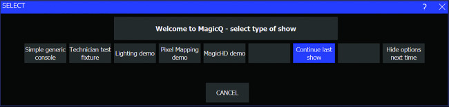
We proceed by registering on the website and downloading the installer. Once the installation is done, we will have several applications of the suite: Open MagicQ PC and wait for a screen to appear, as in Figure 7. Click on Simple generic console. In the new screen that comes up, we go to the menu and select Setup → DMX I/O. In the screen that will appear as displayed in Figure 8, we will be able to set the outputs of the different DMX universes. For the Out Type item, we select Art-Net and choose Art 0 as the Out Uni item. The critical part of the configuration comes when we have to choose the Unicast and Unicast2 items.
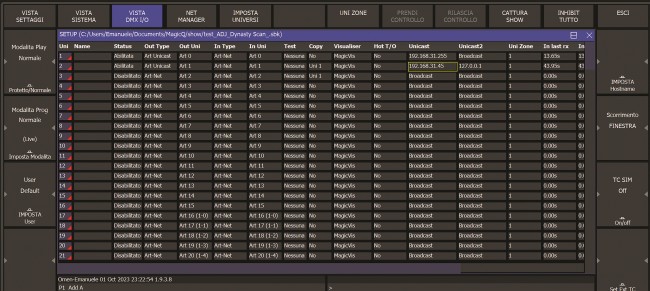
These entries are used to actually indicate to which IP addresses we are going to transmit our packets. Suppose we are connected to a network with a 24-bit subnet (255.255.255.0) and therefore broadcast IP XXX.XXX.XXX.255, we can enter the latter address, and we will be sure that all devices in the network will receive packets. If, on the other hand, we want to avoid flooding all devices in the network by sending packets unnecessarily, we can directly set the IP of the affected device but, in this case, we recommend setting it to use a static IP.
We applied this configuration to the ArtNet 2 universe, which uses the same as Universe 1 as its data source, setting it in the copy column. You can see that we set the localhost address of the PC as in the Unicast 2 field. We entered this configuration so that we could verify the actual packet transmission in debugging software such as ArtNetominator, downloadable from here. We did not enter this option for Universe 1 since, by using IP broadcast, packets automatically “go back” to the PC. Now, let’s go with the cursor to the upper-right and click on Single, sliders will appear as shown in Figure 9.
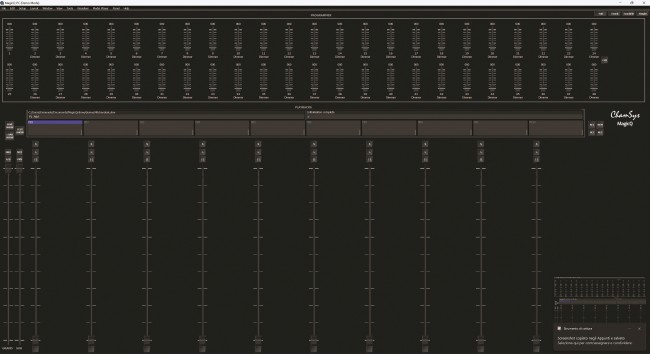
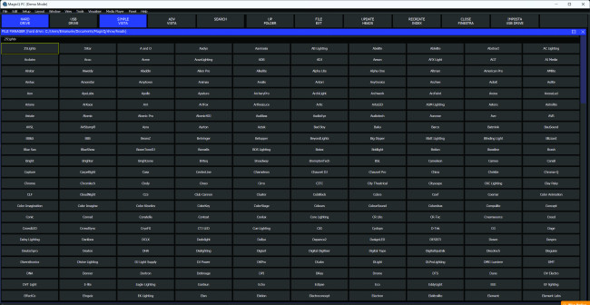
To start packet transmission, we select enable and confirm. Let us now proceed to perform a simple fixture configuration, moving to the left about halfway up the screen and clicking on Test show. On the screen, we will see a long series of cells representing the manufacturers of the fixtures, as in Figure 10. We select the brand and all the pre-configured models available will appear.
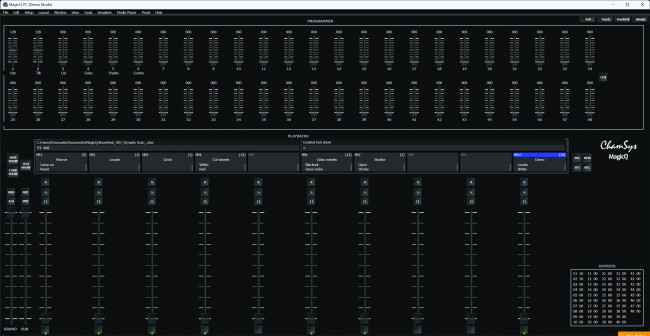
Having made our choice, we’ll see a window like the one shown in Figure 11,in which we will either have individual sliders for basic commands or some macros that include running a mix of them over time. Let’s test the operation, to make sure the devices and software are configured correctly. To take full advantage of the application’s potential, we strongly recommend taking online training sessions that can be accessed for free.
ArtNet to DMX Converter: Final Considerations
We tested the operation of the system under several conditions and found different difficulties, depending on the access points used. In fact, it may happen that — depending on the access point — after a few hours the card goes into an error state and we have to reset it manually. It may happen, considering that this is a hobbyist solution, but by changing devices the problem is solved, allowing the card to work flawlessly for several days. Furthermore, we recommend using a dedicated network to avoid possible system crashes.
DMX Updgrade: Component List
Capacitors
- C1, C4 = 100 nF, ceramic
- C2, C3 = 220 µF, 16 V, electrolytic
- C5 = 10 µF, 63 V, electrolytic
Modules
- U1, U2 = TTL-to-RS-485 converter
- U3 = ESP32
- U4 = MP1584 DC-DC step-down converter, 5 V
Miscellaneous
- DMX1, DMX2 = XLR connector, female, PCB type
- PWR = barrel connector, female, PCB type
- 4× 2-pin strip connector, female, pitch 2.54 mm
- 4× 4-pin strip connector, female, pitch 2.54 mm
- 2× 15-pin strip connector, female, pitch 2.54 mm
- 4× 2-pin Strip connector, male, pitch 2.54 m
- PCB S1716 (102×61 mm)
Editor’s notes: Interested in ESP32 and DIY projects? This project originally appeared in Elettronica IN.


Discussion (1 comment)