
Home Automation Made Easy: From Ding-Dong Door Chime to IoT Doorbell
on
In a previous article, I presented the open-source home automation projects ESPHome and Home Assistant. I also explained how to install them and how to get started. This article shows how I connected the doorbell of our home to the system. The main goal was to detect doorbell ring events in Home Assistant so that they can be relayed to places where the doorbell itself cannot be heard.
The pushbutton of our electromechanical Ding-Dong door chime was replaced many years ago by a wireless door carillon featuring multiple ringtones. It came with two remote stations which greatly increased the range of the doorbell. Unfortunately, everything is powered from batteries, and when these wear out, the carillon becomes unreliable. Also, it tends to confuse visitors as they do not hear anything when they press the button. At our door the postman always rings twice.
As I had recently begun experimenting with home automation, it was a good opportunity to update the doorbell and integrate it into the system. To avoid running cables, I opted for a Wi-Fi connection between the doorbell and the home automation controller.
The old chime itself and its connecting wires, including the power supply, had remained in place. This turned out to be rather practical as the chime offered enough space inside to fit a home-brew wireless doorbell interface in and to power it as well.
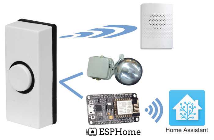
Not wanting to ditch the working wireless door carillon, I decided to use its pushbutton for my new connected doorbell. This way I ended up with a three-generation Wi-Fi-connected door chime/carillon that plays one of several digital ringtones and produces a mechanical Ding-Dong sound at the same time while sending notifications to the cloud (or do some other useful action), see Figure 1.
Audible feedback for the visitor has been restored as well.
Build a doorbell interface
For the Wi-Fi doorbell interface, I chose an ESP8266-based NodeMCU board (Figure 2) because it has an analogue input that I wanted to use (more on this below).
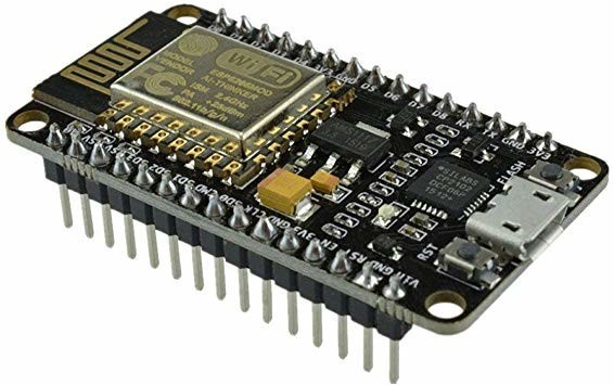
Also, it does not need a USB-to-serial converter, so, besides a soldering iron, no special tools are needed for this project.
As mentioned above, the button of the wireless door carillon is connected to the doorbell interface using the old, existing wires. Because the pushbutton is outside and exposed to the elements, I protected the connection with series resistors, a filter capacitor, and clamping diodes.
The door chime’s solenoid needs about one ampere when powered from 12 volts (AC). This is way too much for the carillon’s tiny tactile pushbutton (such contacts usually can handle only up to 50 mA or so), but with a relay or power transistor it can be done. I used a small 5-volt relay I had lying around controlled by the MCU through a transistor.
The complete schematic is shown in Figure 3.

Monitor a battery voltage
The wire to the carillon’s pushbutton connects directly to the cold side of the pushbutton’s pull-up resistor. This means that when the pushbutton is not being pressed down, the wire carries the voltage of the battery mounted inside the pushbutton’s enclosure. I therefore connected the wire not only to a GPIO pin of the MCU but also to its analogue input. This allows Home Assistant to keep an eye on the wireless doorbell’s battery level as well as relaying doorbell ring messages. This is practical because the wireless range of the carillon is proportional to the battery voltage. When the voltage becomes too low, the remote station(s) can no longer be reached, and the system becomes unreliable.
Note that it is, of course, possible to use the analog input for detecting button presses as well as for monitoring the battery level, but this complicates the firmware. By adding a GPIO pin that was left over otherwise, this complication disappears.
Power supply
The power supply required some attention as the old chime only has a 12-volt transformer while I needed 5-volt DC for the relay and the NodeMCU board.
The chime’s solenoid is quite a heavy load for the transformer, and it makes the transformer's output voltage sag when activated. A large reservoir capacitor filters out the dips caused by the solenoid. Without it, the NodeMCU module reboots at every button press.
The 5-volt regulator is a small 7805-compatible switch-mode regulator which helps to avoid heat dissipation problems.
A power indicator was added too because the NodeMCU board doesn’t have one and it turned out to be practical to have.
By spreading out the doorbell interface circuit over two prototyping boards – one for the power supply, the other for the rest – I managed to fit it all snugly inside the old chime’s enclosure (Figure 4).
ESPHome firmware configuration
The software for the doorbell interface makes use of ESPHome. The advantage of doing so is clear: about 30 minutes of programming (or should I say typing and editing?) is enough to come up with a fully functional device featuring Over-the-Air (OTA) programming, its own web interface and perfect integration into Home Assistant. What’s more, it can be modified at will whenever you feel like it with your smartphone (or tablet or computer).
Programming is not done in C, C++ or Python, but in YAML. YAML is not a programming language, but a markup language that only provides rules to format text. ESPHome takes a YAML script or configuration file as input and transforms it into C/C++ code which is then added to and compiled with the rest of the library. The script specifies the parts from ESPHome you want to include (Wi-Fi settings, web interface or not, things like that), how and which kinds of sensors and actuators are connected to MCU pins, and what to do with them. Most common things are predefined, which makes things pretty easy and quick to set up.
YAML may take some time to get used to, but it is not complicated as long as you respect indentation.
Binding the relay to the pushbutton
The relay that controls the chime’s solenoid is defined as an internal ‘switch’ connected to GPIO14. Specifying it as ‘internal’ makes it invisible for Home Assistant, which avoids cluttering your system.
switch:
- platform: gpio
pin: GPIO14
id: ding_dong_relay
internal: true
The switch is given an ID so it can be used in automations (see below).
The carillon’s pushbutton is a ‘binary_sensor’ on pin GPIO13. As it is active low, we inform ESPHome about it with the ‘inverted’ keyword.
binary_sensor:
- platform: gpio
name: "my doorbell pushbutton"
pin:
number: GPIO13
inverted: true
on_press:
then:
- switch.turn_on: ding_dong_relay
- delay: 200ms
- switch.turn_off: ding_dong_relay
When a pushbutton is pressed, ESPHome generates an ‘on_press’ event which it sends to Home Assistant. However, these events can also be used as signals inside the YAML file to trigger one or more actions. This is called ‘automation’ and constitutes a powerful feature of ESPHome.
Here we use the ‘on_press’ event to produce a 200 ms pulse on the relay output. The relay’s ID is specified here to accomplish this. Now the chime will ding-dong when somebody presses the button, even when the network is down. In short, this restores the original chime as it was installed more than 40 years ago, but instead of just a simple, direct pushbutton connection, we inserted several thousand transistors.
Keep an eye on the battery level
The carillon’s battery is defined as a ‘sensor’ on A0. Its type (‘platform’) is ‘adc’ since it is a voltage that must be converted into a digital value. The NodeMCU module divides the input voltage on A0 by 3.2. In ESPHome, a 'filter' allows modifying a sensor's output value, and a multiplier is considered a filter. Therefore, if we multiply the sensor's value by 3.2, we get the original value back.
sensor:
- platform: adc
name: "doorbell battery level"
pin: A0
filters:
- multiply: 3.2
Specifying lights
The NodeMCU module has a Flash button on GPIO0 and an LED on GPIO16 that can be used too. The Flash button can be a test button; the LED might provide a visual indication that someone has rung the doorbell and Home Assistant saw the event. Therefore, I defined GPIO0 as a binary sensor (added to the binary-sensor section).
light:
- platform: binary
name: "LED1"
output: led1
output:
- platform: gpio
id: led1
pin:
number: GPIO16
inverted: true
Mainly to illustrate the concept, I defined a ‘light’ connected to an output called ‘led1’. This will create a 'light entity' in Home Assistant, which offers other possibilities than a switch does. Also, it has a different icon. The LED itself (on GPIO16) is defined as an output with ID ‘led1’. Note that it is active low (‘inverted’ is ‘true’).
Now, when Home Assistant sends a message to light ‘LED1’ to switch it on or off, the light will forward the message to the output with the corresponding ID, which is ‘led1’.
The complete YAML configuration file for ESPHome can be downloaded from [2]. Note that you will have to change the SSID and password to suite your Wi-Fi network. You may also want to change the name of the device.
Use the ESPHome add-on for Home Assistant
As I have the ESPHome add-on installed in Home Assistant, I wrote the YAML script in the add-on. That way, the device’s YAML file is already in the system, making OTA updates later easy. The first time, however, at least with a virgin ESP8266 system, you must use the serial port to program the MCU since OTA programming has not been activated yet (see inset).
Automation in Home Assistant
The LED on GPIO16 was only declared in ESPHome's YAML file as being available, we did not specify an automation rule for it, and so it will not do anything without intervention from Home Assistant. The idea was to make it light up when someone rings the bell. This can be done with a simple automation in Home Assistant. All it must do is wait for a button press event and switch on the LED when one comes along.
There are several ways in Home Assistant to open the automation editor. One way is to click ‘Configuration’ in the menu on the left followed by a click on ‘Automations’ on the right. Create a new automation by clicking the round orange ‘+’ button in the lower right corner.
You can now enter a phrase to let Home Assistant try to convert it into the desired automation. However, trying to come up with a suitable phrase is not easy and then having to fix the crippled automation rule created by Home Assistant is a waste of time, so here we click ‘Skip’ instead.
Enter a name for the automation, and, optionally, a description. Leave the mode on ‘Single (default)’.
Triggers and actions
There are several ways to specify a trigger event that will start the automation. To me, in this case the most intuitive way is to choose a ‘Device’ as ‘Trigger type’. In the ‘Device’ list, look for the name that you specified in its YAML file. Similarly, search the ‘Trigger’ list for the name that you gave the pushbutton.
There are no conditions, so skip that part.
Actions are similar to triggers, and, like triggers, there is more than one way to obtain the result you are looking for. One way is to choose ‘Device’ as ‘Action type’ and select your device from the ‘Device’ list. From the ‘Action’ list select ‘Turn on LED1’ (if you named the LED differently, use that name instead).
Save your work by clicking the round orange floppy disk icon in the lower right corner.
Check if the automation works by ringing the doorbell. When you do this, and if it worked, you will notice that you have no means to switch the LED off again.
Add a light to the user interface
To remedy this, we will add a so-called card to the Home Assistant overview page. This will not only allow for switching the LED off (by clicking on the card), it also provides a remote view of the LED’s state, so you don’t have walk all the way over to the doorbell to see if it is on or not.
Click ‘Overview’ in the menu on the left. Click the three dots in the upper right corner (‘Open Lovelace UI menu’) and select ‘Configure UI’. Now click the round orange ‘+’ button in the lower right corner (in Home Assistant you mouse around a lot). Look for the ‘Light’ card and click on it. Search the ‘Entity’ list for the LED and select it. Enter a name too as that will make it easier to identify the light in the overview. For now, it may be your only light, but when your home automation system evolves there will probably be more and so a good name will be helpful.
Save the card and leave UI-configuration-mode by clicking the cross in the top left corner (‘Close’).
Clicking the card should now allow you to toggle the state of the LED.
Sounding off
If you followed the steps presented in this article (and corrected any mistakes I made, and adjusted it to the latest versions of the ever-evolving ESPHome and Home Assistant projects), you will now have a Wi-Fi-connected doorbell that you can automate in Home Assistant. You can make it do much more (useful) things than lighting an LED, but I’ll leave that up to you. This article showed the basic principles to get started, and now it is up to you to improve things and adapt it to your needs and desires.
(200089-01)
Interested in Home Automation?
Take out an Elektor membership today and never miss an article, project, or tutorial.
Discussion (0 comments)