
Home Automation Made Easy
on
I had a dream
I for sure had my share of dreaming, but I never really went much further than that because as soon as I began to realize a dream I invariably ran into those practical hurdles that my motivation apparently couldn’t overcome. Building a wireless battery-operated temperature sensor to measure the temperature in the living room isn't terribly complicated, and adding a remote-controlled relay to switch a heater on and off is doable too. But there the complexity only starts. Some sort of controller is needed to allow the creation of basic rules like “on weekdays, switch the heater on at 7 in the morning; in weekends, not until 9.” And it must allow for manual override in such a way that every authorized occupant of the house can adjust the temperature without first having to learn Python.
Up to this point, we can’t even speak of home automation, as this was just the description of a slightly fancy, programmable thermostat. Far more is needed to turn a remote-controlled lamp into a full-blown extendable home automation system. Which is why I never got beyond dreaming.
Espurna & ESPHome
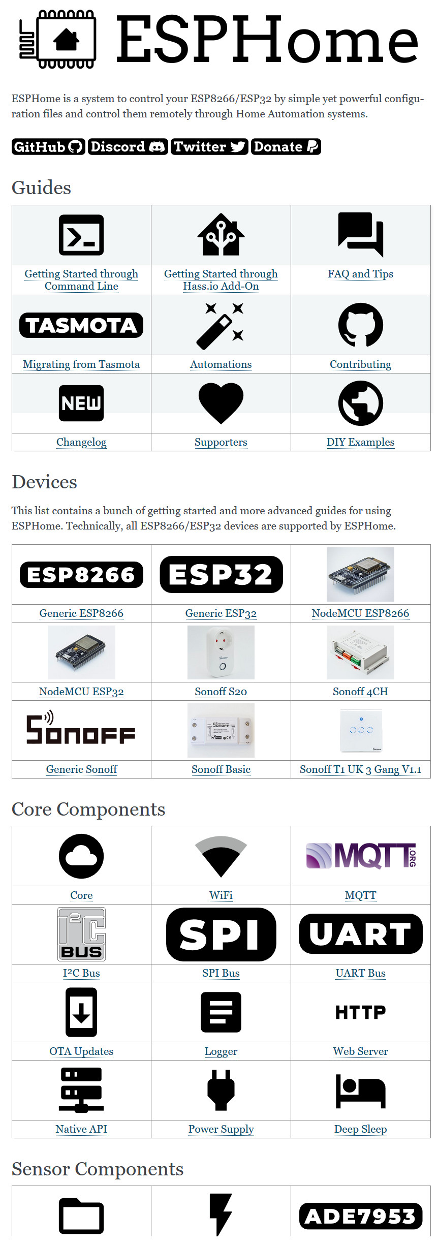
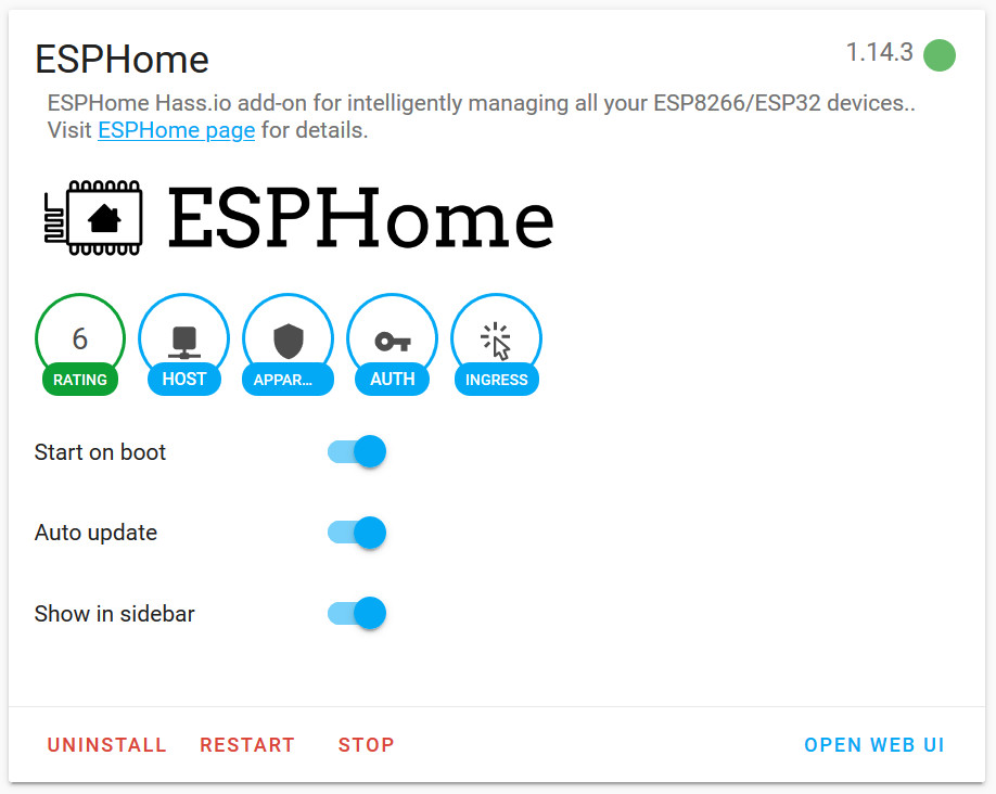
Until recently, while searching online for the manual of a Wi-Fi-controlled power plug I bought a few years ago but never used, I came across the Espurna project (even though I ended up not using it, I am mentioning it here as it is an excellent open-source project that deserves to be known). Espurna allows for the easy creation of Wi-Fi-based (mainly ESP8266) sensors and controllers that can talk to each other. ESPHome (Figure 1) is a project very similar to Espurna.
And you thought Arduino was easy?
Espurna and ESPHome both provide easy-peasy ways of programming Espressif’s ESP8266 and ESP32 devices. In fact it's so relaxed that they make Arduino look like rocket science. In short — after installing the software, of course — you write a simple text file that specifies which kind of sensor is connected to which pin(s) of your ESP module and after compiling and flashing the firmware, you end up with a smart device featuring a web interface, over-the-air (OTA) programming, MQTT communication, and what not. Impressive, isn’t it? I think it is, but it doesn’t stop there.
Take control of your Wi-Fi connected smart plugs
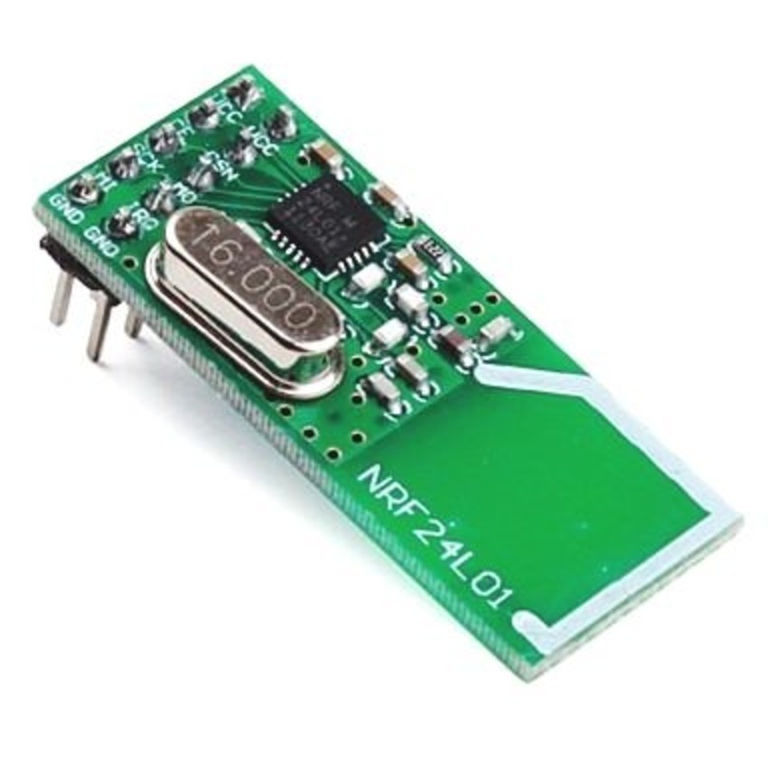
The Internet is afloat with cheap smart plugs and relay boards with on-board Wi-Fi and other Wi-Fi-connected gadgets. Many of these devices are built around the ESP8266 (Figure 2).
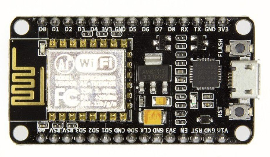
As a common feature, they require an account to a different cloud service somewhere on the Internet, controlled through their own app on your smartphone. This makes them very tedious to use, so much so that these devices often end up in a drawer or, worse, in the bin. No longer, because Espurna and ESPHome let you reprogram these things with firmware that you can modify at will. No Internet connection required. Goodbye broken-English apps and dubious cloud services. Just reflash the darn thing, and integrate it into your home automation system controlled by you@home.
From remote control to automation
ESPHome and Espurna also feature automation, allowing users specify rules for switching equipment on and off following event triggers and sensor data. Both enable you to create a pretty fancy home automation system out of commercially available cheap Wi-Fi–capable hardware or stuff built by yourself.
This article could end here if wasn't for the fact that I found doing automation on Espurna and ESPHome overcomplicated. I am willing to blame this on my limited intellectual capabilities, but only partly, as the lack of good documentation for these projects doesn’t help either. Even though there seems to be quite a lot of it, it is rather fragmented and not always clear.
Home Assistant
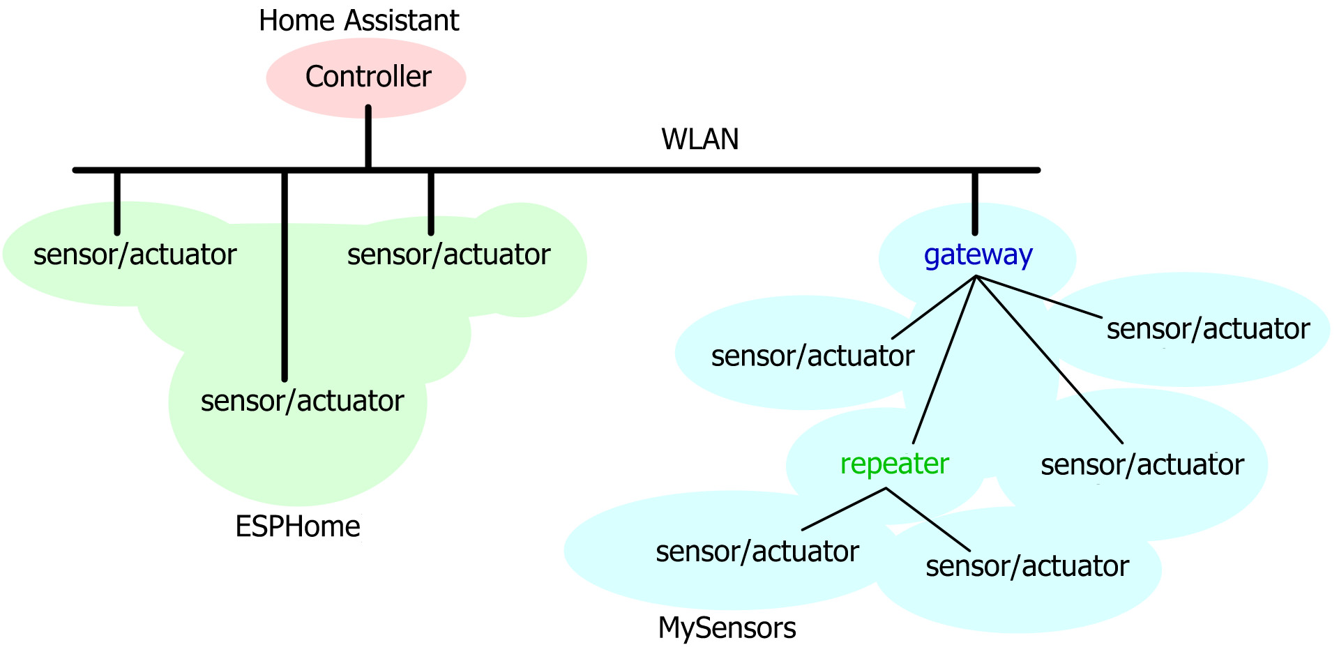
Both ESPHome and Espurna provide integration with Home Assistant, a so-called home automation hub or controller. That's a device allowing the user to combine sensors and actuators (from different manufacturers) within a single system. Here ‘sensors and actuators’ should be regarded in a rather broad sense as they range from thermometers and GPS through Internet services right up to motor control and texting. Home Assistant (also ‘HA’, ‘Hass’ or 'Hass.io') is compatible with — to cite a few well-known names — Alexa and OK Google, Ikea’s Trådfri, Philips’s Hue, Z-Wave and Zigbee Home Automation, and Sonoff by iTead. At the time of writing, HA lists 1574 integrations and goes way beyond the possibilities offered by Espurna and ESPHome.
You use HA to define the rules to govern the appliances in and around your home. “If the sun goes down in 20 minutes and the smartphone of occupant A is inside the house and it hasn’t rained for three weeks, then switch on the third sprinkler from the right.” This is typical (and even basic) HA automation stuff — assuming the concerned hardware is installed and working as intended. HA also provides a fully customizable graphical user interface (GUI) or dashboard for the system (Figure 3).
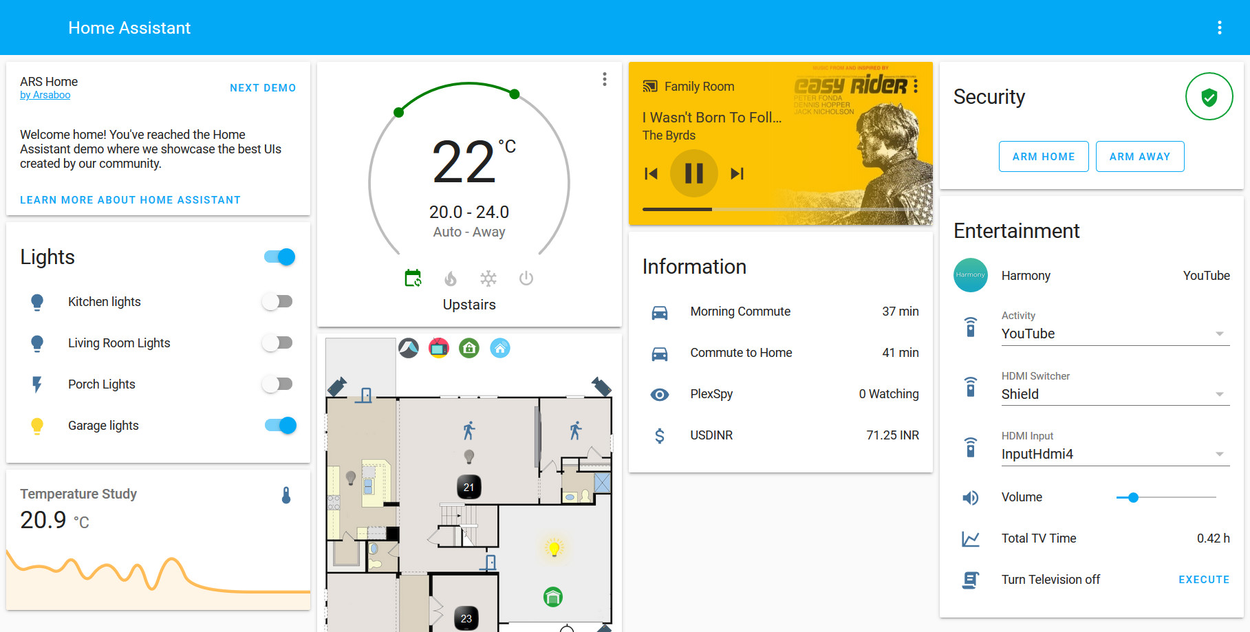
HA is open source, written in Python, and it runs on a Raspberry Pi. It also works on other operating systems; it’s just that I installed it on a Raspberry Pi 3 because that was so easy. You will have understood by now that I am a sucker for easy.
Integration in Home Assistant
Home Assistant was also the reason why I continued with ESPHome instead of Espurna. ESPHome has a plugin (Figure 4) that lets it be integrated in Home Assistant in such a way that ESPHome-based devices are detected automatically by HA.
Flash’n’Play, what more do you want? The integration is pushed so far that you don’t even need a development computer anymore; sensors and actuators can be (re)programmed and (re)configured from your smartphone while sitting in your comfy chair.
Low-power IoT devices
Wi-Fi is great for quickly connecting devices to a network, but it is a tad power-hungry. It is therefore not the best solution for low-power sensor nodes required to run many years off a single button cell, or living off energy harvesting. Such devices spend most of their time sleeping, and when they wake up, they spit out their data as fast as possible since they don’t have the energy for engaging in long handshaking protocols.
A great solution for this type of device is MySensors, an open-source home automation and IoT project based on ISM-band radios, notably the nRF24 by Nordic Semiconductor (Figure 5) and HopeRF’s RFM69.
The more recent nRF5 platform as found on the BBC micro:bit can be used too.
The MySensors website is a slightly messy, but once you manage to see through the noise, you'll notice that there is pretty good stuff available.
MySensors uses mainly (but not only) Arduino as microcontroller platform, and it builds and maintains a tree (or star) network all by itself. Like ESPHome it integrates smoothly (but not as smoothly) with Home Assistant.
The project comes as an Arduino library included in the Arduino IDE’s library manager. After installing it, you can build your application on one of the examples. In many cases this only means changing the pin number(s) of the connected peripheral(s).
Getting your hands dirty
After this long introduction, you may want to get practical, and for this I'd suggest fist setting up Home Assistant on a Raspberry Pi. A good step-by-step guide is available here under the ‘Getting Started’ tab. There the use of a Pi 4 is suggested, but I have HA running on a Pi 3. A 32 GB or bigger microSD card is recommended. Do realize that the Pi cannot handle exFAT-formatted SDXC cards (i.e., SD cards bigger than 32 GB), so if you opt for a 64-GB microSD card (or even bigger), make sure to (re)format it as FAT32. For a more robust system, you may want to use an SSD instead of a (fragile) microSD card.
Multicast DNS
Home Assistant relies on the multicast DNS (mDNS) protocol to find devices and communicate with them, but this protocol isn't particularly well supported by Android and Windows (see inset). Apple devices and Raspberry Pi work fine and I assume computers running some other form of Linux will work too. For this reason, you may want to choose a static IP for HA. My HA system uses DHCP and I have experienced connection problems with the HA app for Android when the HA computer was given a new IP by the DHCP server.
Note that the HA installer quickly launches a web server where you can monitor the installation progress; connecting a display to the Pi isn't useful here. Consult your network’s router to find the IP address of this server.
Gain access to the configuration file
The second installation step is to configure Home Assistant. It has a wizard for this, so I won’t go into details here. More important is the installation of some add-ons after configuring HA. You do this from the ‘Supervisor’ menu under the ‘Add-on Store’ tab. For some reason the default HA setup does not allow you to edit its main configuration file (configuration.yaml) yet you will find yourself having to do it regularly, especially when you are experimenting with the system. I therefore installed the ‘File Editor’ add-on (formerly known as ‘Configurator’) and also ‘Samba share’. The first lets you edit low-level files directly in HA. The second exposes some HA folders on the network, allowing you to, for example, edit files with your favourite text editor. For security reasons, you may want to install the ‘Terminal & SSH’ add-on instead. Samba also allows you to use HA as a file server if you create a ‘www’ folder in the ‘config’ folder.
Installing add-ons is straightforward, just click on the add-on’s card to open it and then click install. An opened card contains instructions on how to configure the add-on.
Installing the ESPHome add-on
This brings us to ESPHome, because we should also install the ESPHome add-on. To get this done, first add the repository’s URL to the store. Then locate the box saying ‘Add new repository by URL’ and paste the following URL into it:
https://github.com/esphome/hassio
Now you can install the ESPHome add-on. There are three versions: plain, beta and dev. We will use the plain vanilla version. The only configuration I did for this add-on was enabling the ‘Start on boot’, ‘Auto update’ and ‘Show in sidebar’ options. The latter is practical as it makes accessing the add-on much easier.
Integrating MySensors
At the time of writing, there was no Home Assistant add-on for MySensors. Activating this integration in HA is therefore done by adding a few lines to the HA configuration.yaml file (see inset):
mysensors:
gateways:
- device: '192.168.1.100'
persistence_file: 'mysensors/wifi_gateway.json'
tcp_port: 5003
optimistic: false
persistence: true
retain: true
version: '2.0'
As indicated, you have to choose a static IP for the MySensors gateway you are going to build (yes, you are, see below), and you have to choose a name and location for the JSON file where HA can store MySensors network information.
Important: Every time the HA configuration.yaml file is modified, the system needs a restart for the changes to take effect. This can be done from the Supervisor’s ‘System’ tab.
Now that you’re editing the configuration file, you might as well add the following (saving a restart):
binary_sensor:
- platform: workday
country: [country]
These lines enable writing automation rules that only fire on workdays or weekends, things like that. Replace [country] by the code of the country the system is working in. Refer to the help page of the ‘Workday Binary Sensor’ to find this code (and other useful information).
My first ESPHome device
If you followed the instructions above, then you are now set to program ESP8266- and ESP32-based devices. Because a new (virgin) device is not yet compatible with ESPHome, initially it has to be programmed over the serial port. Depending on the device, you may have to install a USB-to-serial-port driver on the HA computer to make this work. The NodeMCU boards with a Silabs (Silicon Laboratories) CP2102 USB chip that I used worked straight out of the box.
After connecting the device to the computer running HA, open the ESPHome Dashboard either from the sidebar (if you enabled this option) or by clicking ‘Open Web UI’ from the add-on card in the Supervisor Dashboard view. Check that the serial port is available from the drop-down list in the upper-right corner that defaults to ‘OTA (Over-The-Air)’. If it doesn’t, restart the ESPHome add-on (by going back to the ESPHome card on the Supervisor Dashboard), that should do the trick.
The next step is to click the pinkish ‘+’ button on the ESPHome Dashboard. This will open a wizard to guide you through the first part. Note that I have never specified an access password for any device, but maybe I am being irresponsible. For the upload port, select the serial port to which the device is connected.
Editing the YAML file
The wizard is now done and a card should have been created for your device. At this point clicking its ‘Edit’ button never works (for me), but after reloading the page it does. Click it and check the credentials for your Wi-Fi network and make sure you see the lines ‘api:’ and ‘ota:’. If you upload this configuration to your device and reboot it, it will be detected by Home Assistant. It can now also be disconnected from the computer because over-the-air programming has been enabled. The device will not do anything, though, because you did not configure its peripherals. Therefore, read on before uploading a configuration.
If you use a NodeMCU module, you can kickstart it by adding the lines below to the end (below ‘ota:’ for clearness sake, the position in the file doesn't matter) of the configuration file before uploading it. It will give HA access to the on-board LED and the ‘Flash’ pushbutton.
output:
- platform: gpio
id: "led"
pin:
number: GPIO16
inverted: True
light:
- platform: binary
name: "LED"
output: "led"
binary_sensor:
- platform: gpio
name: "Flash pushbutton"
pin:
number: GPIO0
inverted: True
Note that in this snippet every level of indentation is two (2) spaces, meaning that the lines ‘number: GPIOx’ and ‘inverted: True’ start with six spaces (as they have three levels of indentation, see inset).
This config can also made to work with an ESP-01 module if you change ’GPIO16’ to ’GPIO3’ and connect an LED in series with a 470 Ω (or so) resistor between GPIO3 (RXD) and ground. Also connect a pushbutton between GPIO0 and GND and a 10 kΩ (or so) pull-up resistor between GPIO0 and 3V3. Do not press this button when booting the device.
Upload this configuration to the ESPHome device and wait for it to restart. Home Assistant should see it — the ESPHome dashboard should show it as ‘Online’ — and, if you let it, create a control for a light and an indicator for the pushbutton. If you uploaded the empty configuration first, then you may have to go into HA’s ‘Configuration’ menu to look it up in the ‘Devices’ list.
You can now add cards for the controls to HA’s ‘Overview’ (click the three dots and then ‘Configure UI’) and create automations in the ‘Automation Editor’ on the Configuration menu (‘Automations’). I leave this to you as it is quite self-explanatory and a good excuse to browse around in Home Assistant. Also, MySensors is waiting for us.
Build a MySensors Wi-Fi gateway
A gateway is required to build a MySensors network and you also need it to connect to other (Wi-Fi) networks. For this I used an ESP8266-based NodeMCU because it exposes an SPI Port which we are going to need. Using an ESP32 module is another option. Actually, there are many options, but in this article we are going for Wi-Fi.
Connect the SPI port to an nRF24L01+ module (Figure 6).
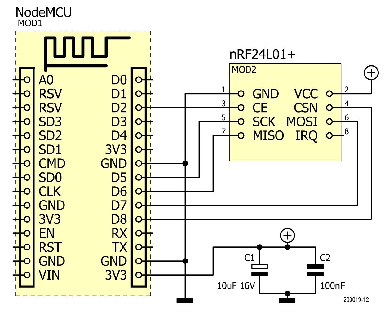
It is recommended to also add an electrolytic capacitor (4.7 to 47 µF) together with a ceramic one (100 nF or so) between the VCC and GND pins of the nRF24 module. That’s all the 'electronics' you'll need.
On the software side a computer with the Arduino IDE installed is required. Add to the IDE the ESP8266 (or ESP32) core for Arduino — all the details are here — and the MySensors library (‘Sketch’ ‘Include Library’ ‘Manage Libraries…’). Load the example ’GatewayESP8266’ (‘File’ ‘Examples’ ‘MySensors’) and enter the correct SSID, password, and the static IP that you specified earlier in HA’s configuration.yaml file. Upload the sketch to your device, and your gateway is ready.
Please keep in mind that a gateway (and repeater nodes, not treated in this article) must always be powered and may never sleep. Sensor nodes can do whatever they want.
My First MySensors Node
Creating a MySensors node is not unlike building a gateway, except that the ESP module is replaced by an Arduino-compatible board with sensors and actuators added to it. Connect an nRF24L01+ module to the board’s SPI Port, and add the capacitors mentioned above (Figure 7).
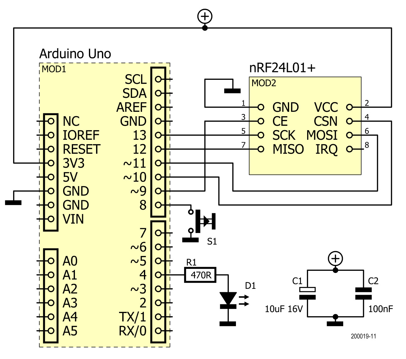
Load an example sketch from the MySensors example library, preferably one that resembles what you are trying to achieve. Note that there are more examples on the MySensors website. The sketch requires adapting to fit your peripheral(s) pin number(s), but basically that is all there is to do. Upload the sketch to your device and let it boot; it will join the MySensors network automatically (if the gateway is on). Really.
Beware of the protocol version
At this point I ran into the problem that my device, a remote relay, did not show up in Home Assistant. Eventually I discovered that this had something to do with the version of the MySensors API being used. By inspecting the persistence JSON file (see section ‘Integrating MySensors’), I noticed that the gateway was listed as using API or protocol version 2.3.2. The MySensors page has an example intended for use with API versions 2.x. When I tried that one, my node appeared in the ‘Entities’ list on HA’s ‘Configuration’ menu and I was able to create UI cards for it.
According to the MySensors page, to make a V2.x-based node work in HA, it must send an initial value from the function loop(). The example sketches do not do this. However, delving deeper I surmised that an actuator node must request (and maybe also send) an initial value from HA in order to be recognized. A sensor node is reported as soon as it starts sending data. The request doesn't have to be made from loop(), but simply somewhere during the boot process.
Special functions 'before()' and 'presentation()'
To distinguish V2.x-sketches from older types, look for the function presentation(). If the sketch has one, it is V2 or higher. However, the other way around is not true as presentation() may be left out. The present instructions usually found in this function may not be omitted and must be moved to another function, for instance to setup().
MySensors sketches can have a function before(). Both before() and presentation() are called before setup(), and in this order, i.e. before(), presentation(), setup(), and finally loop().
Adapting existing code to your hardware is now quite easy. Many examples for all sorts of popular sensors are available, either in the Arduino library or online, so look around before diving in head-first.
OK that’s it, I hope you found it interesting
Here Endeth the Lesson on easy home automation (Figure 8).
Please keep in mind that it is not complete and that there may be better or easier ways of doing things. My understanding of the components involved is still evolving.
Furthermore, there are many other home automation projects that can do the same or similar things as the ones mentioned in this article. Some may be better, others may look nicer; they all have their strong and weak points.
Because there are so many, it's hard to choose which one(s) to use. In this article I have presented a few that I have tried and kept to build my home automation system on. I still use them, and I am still amazed by the endless possibilities they offer. Stay tuned, because I do not plan to stop here.
At Elektor Labs you can find example configurations for ESPHome and MySensors devices. There are also some videos.
(200019-01)
More on Home Automation
Want more great Elektor content like this? Take out an Elektor membership today and never miss an article, project, or tutorial.
Discussion (0 comments)