Capacitive touch interfaces really took hold after their success in the Apple iPod with its rotary wheel. Since then, touch buttons have made their way into almost every household appliance, industrial application, and even our cars. Here we explore the principles of capacitive touch and the challenges of making it robust enough for deployment in a real application.
One day, we were all quite happy with mechanical buttons. Then, in 2003, an Apple iPod with an all-touch interface appeared. Seemingly overnight, the minds of product marketers worldwide were blown, and everything from washing machines and coffee makers to car door handles had to have a touch interface.
Much of the success of the iPod can be attributed to its touch-controlled user interface. Behind its shiny ring and its glowing buttons were capacitive sensors. Evaluated many times per second, any change in their capacitance indicated the presence of a finger to signal a press or a rotation. Of course, the phenomenon used was nothing new. The influence of human body capacitance on electronic circuits was discovered in 1919 when Leon Theramin used it for controlling a heterodyne oscillator in his instrument of the same name.
Impact of Capacitance on Circuits
Those with experience in electronics will probably have experienced the impact a finger has on a circuit. Audio and radio circuits often respond to the presence of a finger by changing their output pitch or tuning to a different radio station. I once heard of someone discovering their radio receiver suddenly operated as expected by placing their finger on one of the valves. Being uninclined to place the said finger in the back of the radio forever, they replaced it with a sausage which provided good service for some time and a surprise for the technician who eventually had to replace the pork product with an actual repair.
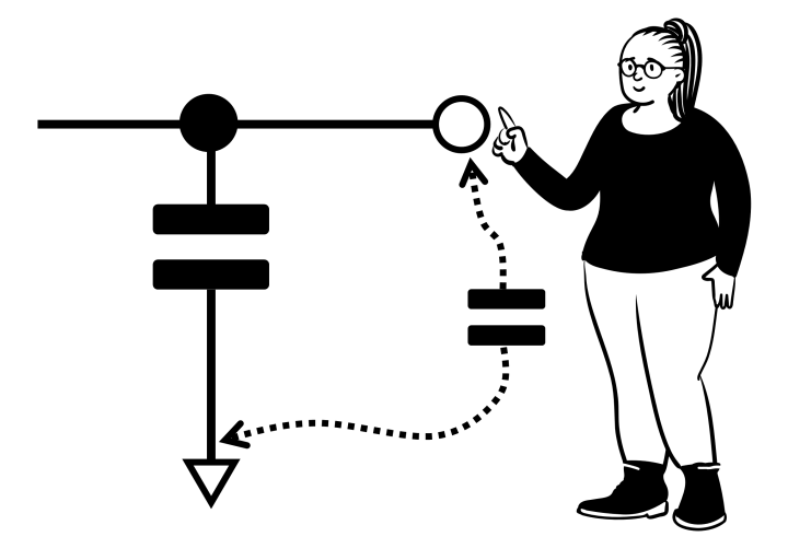
Capacitive touch circuits rely on the change in capacitance a finger or body part has on the function of a circuit. The presence of a finger forms a parallel capacitance to ground that increases the value of the capacitor in the circuit.
The human body introduces a small, parallel capacitance when touching circuitry.
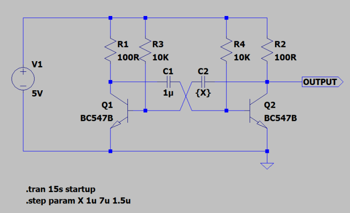
One approach could use the capacitors in an oscillator. In this example, we vary the value of C2 between 1 µF and 7 µF in steps of 1.5 µF to simulate the introduction of a parallel capacitance.
An astable circuit could use one of its capacitors as a touch sensor. In this simulation, C2 is varied to demonstrate the effect.
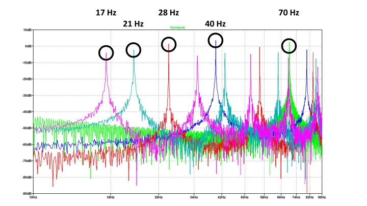
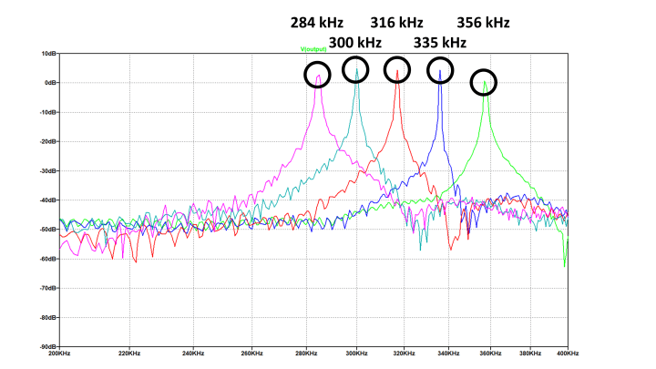
Looking at the output’s FFT (fast Fourier transform), we can see the frequency starts at 70 Hz, dropping to 40 Hz, 28 Hz, 21 Hz, and then 17 Hz in response to these changes. It should be noted that the output is a square wave, so many harmonics are obscuring the view.
As the capacitance increases, the frequency drops. This could be used to detect a finger touching our capacitive sensor.
Here we have the beginnings of a touch detection circuit. The output could be connected to a counter. The difference between touch and no-touch can be determined by counting the number of pulses in a specified time period, say 100 ms, and setting a count threshold. Another approach is to measure the variation in on-pulse widths.
At this point, real life comes into play as we try to implement such circuits. The human body forms a capacitance of somewhere between 100 pF and 200 pF. Replacing C1 in our circuit with a 300 pF capacitor and sweeping C2 between 100 pF and 200 pF, the output changes from 356 kHz with no human touch, dropping to 284 kHz in the presence of maximum human-body capacitance. It should be noted that this is only a simulation, and the transistors selected may not operate at this frequency in reality. However, we have the makings of a capacitive touch sensor.
Using the tiny capacitances of the human body, our oscillator operates closer to 350 kHz before being touched.
Types of Capacitive Sensor: Self-Capacitance
There are two types of capacitive sensing: self-capacitance and mutual capacitance. Self-capacitance is the approach described above, where the touch sensor forms a capacitor to ground, and the circuit measures the change in its value when a finger is placed on it. Rather than use the capacitor as part of an oscillator, touch circuits typically use approaches that can more accurately control the charge applied.
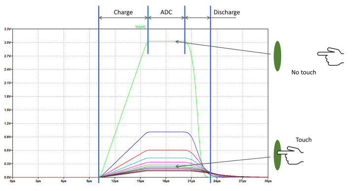
One example is the Charge Time Measurement Unit (CTMU), a peripheral in some of Microchip’s microcontrollers. It works by applying a constant charge (0.55 µA, 5.5 µA, or 55 µA) to the sensor for a fixed period. Once this period is over, the voltage on the sensor is measured using an analog-to-digital converter (ADC). With the ADC measurement complete, the sensor is discharged completely, allowing the process to be repeated. This is replicated approximately in the circuit below.
The Microchip CTMU consists of a current source plus a switch to discharge the sensor capacitor.
Like any analog sensing application, the measured signal will be influenced by interference, and some filtering will be necessary to detect a finger touch accurately. In the measurements below, an approaching finger reduces the peak voltage attained at the sensor.
The CTMU delivers a lower voltage in the presence of a touch at its sensor.
Self-capacitance touch sensors are typically used when only a limited number of buttons are required or for proximity detection. Grouping sensors together, they can form rotary interfaces or sliders. Interleaving the copper pads on the circuit board can smooth the transition between the individual sensors.
More complex sensors like sliders (top) can deliver 'bumpy' results. Interleaving the sensors (below) can help to improve the smoothness of the output.
Interference is tackled by applying ground rings around the sensor or placing a hatched ground behind the sensor. However, care must be taken to avoid reducing the sensitivity too far. The size of the sensor is also important. Ideally, the sensor area should match that of a human fingerprint, somewhere between 8 and 20 mm in diameter.
Capacitive sensors are typically implemented behind a plastic cover. The thicker the material, the lower the sensor sensitivity. Finally, many surfaces, such as the user interface of a washing machine, are curved, while a printed circuit board is typically flat. Flexible PCBs on polyimide can be used to resolve this, but flex PCBs are expensive. Alternatively, the distance between the touch surface and PCB can be bridged using springs or conductive foam. While this resolves the issue mechanically, extra testing and further tuning of the circuitry and software are needed to ensure reliability.
Subscribe
Tag alert: Subscribe to the tag IoT & Sensors and you will receive an e-mail as soon as a new item about it is published on our website!
Types of Capacitive Sensor: Mutual Capacitance
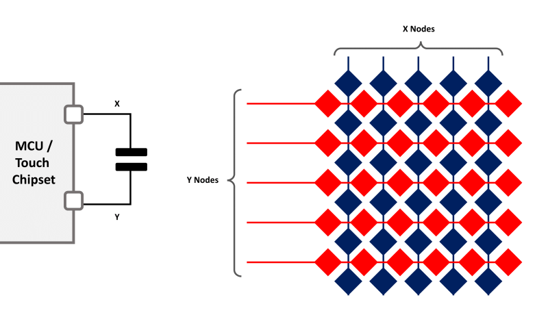
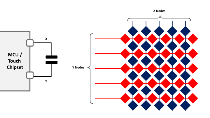
Mutual-capacitance sensor approaches use a capacitive sensor connected between two pins of the touch chip or a microcontroller, measuring the change in charge with and without the presence of a finger. The finger essentially steals charge from the capacitor as if it were being placed between the two plates. Thus, a touch appears as a drop in capacitance. This approach allows the creation of a grid of capacitors across flat surfaces to support touch screens, which is typically termed projected capacitive touch or PCAP. One method charges the X rows of the sensor area sequentially, evaluating the capacitances using the Y rows, with each cycle occurring tens of times per second. This is the preferred capacitive touch approach used for the screens of smartphones and touchpads on laptops.
Mutual capacitance implements the capacitive sensors between two pins of the microcontroller or sensor IC (left). Touch screens and touchpads use a grid of diamonds or similar patterns to implement a touch surface (right).
The diamond grid pattern is a good starting point and works well in copper. Ideally, both the X and Y rows should be on the same side, requiring a lot of through-hole connections for either the X or Y rows. Other patterns may also be used depending on application demands, such as size and sensitivity. In smartphones, the pattern is applied to the glass cover above the display using Indium-Tin Oxide (ITO). This material has a relatively low resistance, and it’s transparent, minimizing the impact of screen legibility and loss of brightness. Other materials, such as ultra-fine copper tracks on transparent foil, have also been used. To avoid impacting the visual effect of the display, the copper tracks are applied to lie between the rows of the display’s pixels.
These applications make use of dedicated chipsets, such as MaxTouch. Designers appreciate such fully-featured solutions as they can evaluate hundreds of capacitances per second and apply the necessary filtering. At their output, they reduce user interaction into X-Y coordinates for each finger and can even provide the gestures used (pinch, swipe, rotate). In the application software, this sensor data is treated much the same as other input devices, such as a mouse, without worrying about decoding gestures and removing noise from the signals.
Adding capacitive touch to Arduino and Raspberry Pi
Ready-to-use capacitive touch ICs are available from Microchip, Azoteq, and Texas Instruments. These greatly simplify circuit construction, typically providing a digital output or serial interface that interfaces directly with an Arduino or Raspberry Pi. However, it should be noted that successful deployment in an actual application requires much testing with different sensor designs and configurations to ensure long-term robustness and reliability. Alternatively, libraries are available for Arduino that enable the creation of capacitive sensors using just a resistor. This is more than enough to enable students and makers to create touch interfaces for exploring interface concepts and trying out ideas rapidly.
Elektor Magazine has been one of the leading sources of information on electronics for engineers, designers, start-ups and companies for 65 years. Our magazine is powered by an active community of electronics engineers – from students to professionals – who are passionate about designing and sharing innovative ideas.
For them, we publish hundreds of items a year, in formats such as articles, videos, webinars, and other learning formats. Our mission is to share knowledge in every possible way and inspire readers with the latest developments within the electrical engineering sector.
Thank you for your vote!
Leave further comments in the fields below.
Thank you for your vote!
If you wish to leave a comment with your rating, please first use the login below. If not, just close this window.


Discussion (0 comments)