
MicroPython for the ESP32 and Friends (Part 1): Our First Programs
on
This article will look at the basics of MicroPython, and in particular at the most important commands and libraries available. We will use an ESP32 microcontroller to demonstrate a couple of small applications: the microcontroller will be programmed with firmware that interprets the Python commands. The Python program itself is written using a development environment that runs on a PC, and Python commands can be sent from the PC to the microcontroller either as an entire program or one at a time. That can be done either over USB or over a wireless network. Let’s look at these aspects one by one.
Programming and Development Environments
In contrast to the Arduino ecosystem, MicroPython can work with a range of integrated development environments, or IDEs. Currently, the two most widely-used environments are µPyCraft and Thonny. Also, we might consider installing Anaconda Navigator, which is primarily used for programming microcontrollers in the field of artificial intelligence. Each approach has its own particular advantages and disadvantages. For example, the μPyCraft IDE offers only a comparatively unsophisticated user interface, using simple graphical elements reminiscent of text-oriented operating systems.
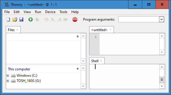
Thonny, on the other hand, offers a complete graphical user interface in the style of Windows (see Figure 1). This IDE is very popular in the maker community, in particular because it is available for the Raspberry Pi running under the Raspbian operating system. Many Raspberry Pi users are therefore already very familiar with Thonny. Thonny runs on all the major operating systems including Windows, Mac OS X and Ubuntu Linux, and is available for free download on the Internet.
Before using Thonny it is necessary for Python 3 to be installed on the machine that will be used for development. If that is not already present, you can find the installation instructions on the relevant website.
Next, we can install Thonny itself from [1]. First select the appropriate operating system at the top right of the page. Launching the downloaded file will start the usual installation process. The IDE is now ready to develop our first Python application.
Installing the Interpreter
The next step is to install the MicroPython firmware itself. This can be obtained from the official MicroPython website, where you will find a range of microcontroller options available. In this article we will be looking specifically at the ESP32, and so we need to download the latest version compatible with this microcontroller type. Under Espressif ESP-based boards click on the image whose caption is Generic ESP32 module. The page that now opens offers a number of different firmware variants. Notice that the most recent version of the firmware is often marked as ‘unstable’. This option is aimed rather at the developers of the interpreter firmware itself and others of an adventurous disposition. Those of us who prefer a more stable system should select the most recent version that is not marked as ‘unstable’, for example:
GENERIC : esp32-idf3-20200902-v1.13.bin
Click on the appropriate link and the firmware will be downloaded.
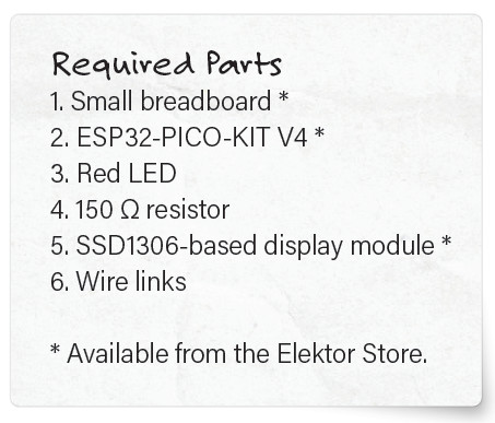
Now we can connect the microcontroller board (for example, an ESP32-PICO-KIT: see the Required Parts text box) to the PC over USB and then launch the Thonny IDE.
Here we need to choose the Select interpreter entry in the Run menu, which opens the Thonny options window: see Figure 2.
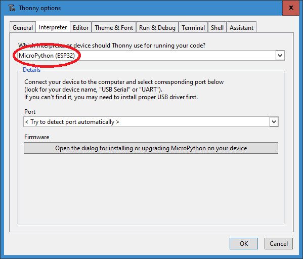
Under the Interpreter tab there is a range of options to choose from, including ones specific to the ESP32.
Under Port select the USB port to which the ESP32 is connected. Alternatively, you can select the option Try to detect port automatically. This, however, does not work reliably in every case.
Clicking in the box under Firmware will now start the installer. The port is not configured automatically and must be entered again. Then navigate to the firmware that we downloaded above. Clicking on Install will start the installation process. When the process is completed the window remains open: close it and you are ready to start programming your ESP32 in MicroPython.
Libraries
Working with Python means working with libraries. Writing every program from scratch is, to say the least, highly inefficient, and the overwhelming success of Python is in large part down to the range of libraries available for it. Unfortunately, not all libraries can be operated within the confined resources of a microcontroller, and so a special selection of libraries has been developed for use with MicroPython. Many of these are available as a standard part of the download of the Thonny IDE.
The two most important standard libraries in MicroPython are machine and time. The import command is used to make the libraries available for use on the microcontroller. The following approaches (among others) can be used to make a library function accessible:
- import module
- from module import name
In the first case, the whole module is imported; in the second case, only the specified functions are brought in.
The machine module contains functions specific to the hardware of a particular microcontroller. These functions allow direct and unfettered access to and control over hardware components including the CPU, timers, buses and input/output pins. Be aware that misuse of this module can cause errors, crashes, and, in extreme cases, even damage to hardware.
The Pin class is one of the most important parts of the machine module. A Pin object is used to control an input/output pin and conventionally a Pin object is assigned to a physical pin on the microcontroller. The object allows output levels to be controlled and input levels to be read.
The Pin class provides methods to set the mode of the pin. For example, IN and OUT can be used to configure a pin as an input or an output respectively.
The time module provides a range of time-related functions. The sleep class from this module pauses the execution of the running program for a specified number of seconds. The argument can even be a floating-point value, allowing exact delays of a fraction of a second to be specified. The commands
from machine import Pin
from time import sleep
make the Pin and sleep functions available. With the first of these we can talk to the individual port pins of the microcontroller, and with the second we can implement time-based functionality. Using the command
led = Pin(2, Pin.OUT)
we can create an object led which is associated with I/O pin number 2, and configure this pin as an output. We can now pass various values to this object. For example, if we execute the command
led.value(1)
then the value 1 will be written to the object. In turn that means that the associated I/O pin, pin 2, will be set to a high voltage level. In the case of the ESP32 this is 3.3 V.
The REPL Console
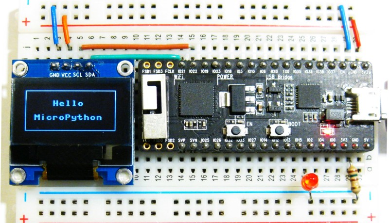
It is possible to monitor the state of a port pin by simply connecting an LED to it via a current-limiting resistor. (Figure 3 shows how this is done, as well as how we can go a step further, connecting up a full OLED panel: more on that later.)
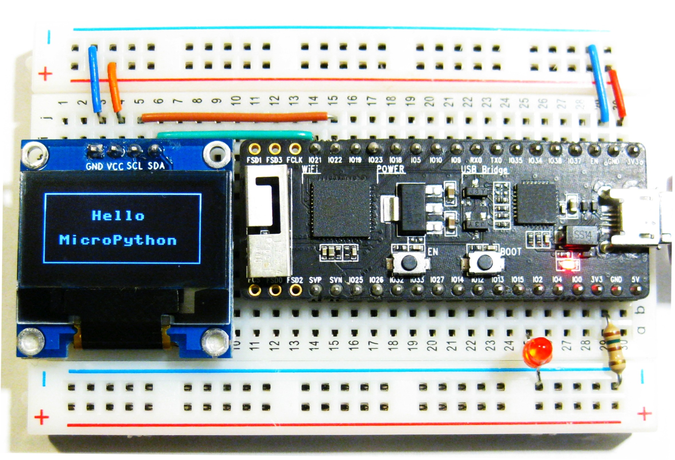
The port, and hence the LED, can be controlled very simply using what is called the ‘REPL console’. REPL stands for ‘Read Evaluate Print Loop’, which is an interactive MicroPython entry method that allows us to execute commands directly on the ESP32. The REPL console thus gives us a very simple way to test out commands and execute programs.
The REPL console is called the ‘shell’ in Thonny and is available at the bottom right of the main window. You can enter the commands from the excerpts above directly in this box: see Figure 4.
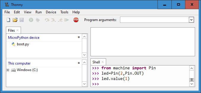
After entering the last of the above commands the LED should light up. The command led.value(0) can be used to turn the LED off again.
The REPL console has a few interesting features that make working with MicroPython very convenient. For example, previous command lines are stored, and the up and down arrow keys can be used to recall previously entered commands are required.
Another handy feature is tab completion. Pressing the ‘Tab’ key on the keyboard will automatically attempt to complete a partially-entered word. This can even be used to obtain information on the functions and methods available in an module or applicable to an object.
For example, entering ‘ma’ and pressing the ‘Tab’ key leads to an automatic completion to ‘machine’ (assuming that the machine module has already been imported as described above). Now pressing the full stop key (‘.’) and then ‘Tab’ again will bring up a complete list of all the functions available in the machine module: see Figure 5.
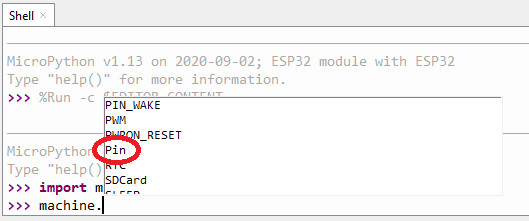
This feature in many cases makes it unnecessary to look up commands, objects and methods in the documentation.
Wireless Access Using WebREPL
One of the major advantages of the ESP32 is its excellent support for wireless connectivity. So what could be more natural than to make the REPL console available over such a connection? To do this we can use the WebREPL interface.
The first step to get WebREPL up and running is to ensure that it is installed and enabled on the ESP32. By default WebREPL is not enabled and must be switched on using the one-time command
import webrepl_setup
over the serial port. You will be offered the options of enabling or disabling the feature, and for setting a password. After configuration the ESP32 must be rebooted.
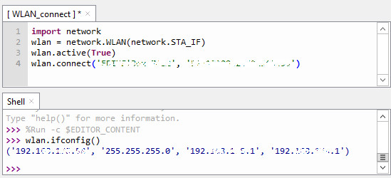
To use WebREPL over a wireless network the ESP32 must first be connected to that network. To do that, issue the following commands to the serial REPL console.
import network
wlan = network.WLAN(network.STA_IF)
wlan.active(True)
wlan.connect('ssid', 'password')
The placeholders ssid and password should of course be replaced with the credentials for your local wireless network. The command
wlan.ifconfig()
will then display the IP address settings which the ESP32 is using to communicate with the network: see Figure 6.
The commands
import webrepl
webrepl.start()
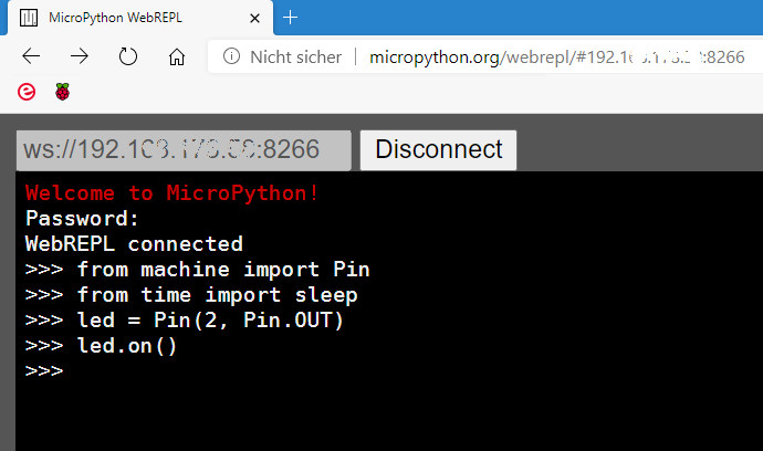
will now enable the WebREPL client. In a web browser you can go to the address
http://micropython.org/webrepl/#xxx.xxx.xxx.xxx:8266
where for xxx.xxx.xxx.xxx you should substitute the IP address determined above using the wlan.ifconfig() command. You can then use the Connect tab to connect to the ESP32 using the password that you previously configured as part of the setup process.
When WebREPL is started up, you may find that the console is in ‘raw REPL’ mode. This allows the direct entry of commands using copy and paste. In such situations, you can press control-B to switch to normal mode, which allows for normal entry of commands.
We are now in a position to control the ESP32 entirely wirelessly. The simple output switching commands already allow us to implement basic home automation functions: see Figure 7.
If a suitable file system is installed on the ESP32 it is also possible to perform software updates wirelessly, also known as over-the-air (OTA) updates. When working with WebREPL, it is worth bearing in mind that it is something of an experimental feature, and so might not be expected to work absolutely reliably in all situations.
Program Control
The REPL or WebREPL console is best suited for testing out ideas. For conventional program development the editor panel (above the REPL console in the Thonny window) is more suitable. There we can for example prepare the program described below which is designed for automatic control of night-time lighting and stairwell illumination: see Figure 8.
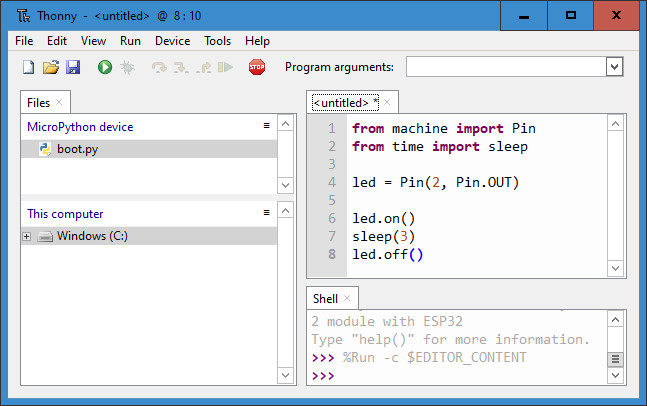
Once the code has been entered and started using the start icon (white arrow in a green circle), you will be prompted to save the program. Here, choose the option MicroPython device and enter a program name (for example, Automatic_LED) and confirm the save operation. The LED will now light for three seconds and then automatically extinguish. If you press the start button again, the program can be re-run immediately.
To turn this into the classic ‘blinky’ flashing LED demonstration program, we simply need to add a while statement. This will cause a given command or block of commands to be executed repeatedly. The particular case of while True: creates an endlessly-repeating loop: in this case, that means that the LED will flash continuously.
from machine import Pin
from time import sleep
led = Pin(2, Pin.OUT)
while True:
led.on()
sleep(0.5)
led.off()
sleep(0.5)
Observe here that the while statement must be terminated in a colon. The following block of commands is, in accordance with the standard Python convention, indented by a constant amount of white space. Thonny provides this indentation automatically: as soon as you enter a colon followed by the Return key, the cursor will appear in the next line indented by one step. And of course, the program editor also offers the tab-completion feature. A running program can be halted by pressing control-C.
MicroPython in a Nutshell
Although the lifeblood of MicroPython is its collection of libraries, a decent grasp of the basic commands is necessary to understand others’ programs and to write one’s own. We will therefore now look briefly at the most powerful MicroPython commands.
Simple comments are introduced by the ‘#’ symbol. The comment runs from the ‘#’ to the end of the line.
>>> print("hello ESP32") # this is a comment
hello ESP32
Comments are ignored during program execution; they are only there to provide information to the program developer. The print() command used here allows information to be output to the console, whether text-based or numerical; on the other hand, you can also call print() directly from the terminal window.
As we saw above the in LED ‘blinky’ example program, statements can be grouped together into blocks identified by their indentation. That means that braces (‘{‘ and ‘}’) and other similar mechanisms are not needed. The advantage of this approach is one is more or less forced into a structured programming style.
It is very easy to create a variable in MicroPython, and in particular it is not necessary to specify the type of a variable. Variables can also be used directly in the console as follows.
>>> a=17
>>> b=12
>>> print(a*b)
204
In MicroPython the arithmetic operators have their conventional mathematical interpretations. Besides addition, subtraction, multiplication and division we also have the // operator for integer division, % for modulo (or remainder from division), and ** for exponentiation.
The usual branching and looping statements are also provided in MicroPython. Branching is supported by the keyword if, followed by a condition; if the condition is true then the next statements are executed. An else keyword may follow, introducing a set of statements to be executed instead if the condition is false. For example:
if True:
# block 01
print ("True")
else:
# block 02
print ("False")
Loops provide a facility to repeatedly execute statements. A set of statements is executed for as long as a specified condition is fulfilled. Two variations are available:
• ‘while’ loops
• ‘for’ loops
So, one way to print the numbers from 1 to 9 on the console would be to use a while-loop as follows.
number=1
while number<10:
print(number)
number=number+1
The set of statements to be repeated is indicated by the indentation. This task can equally be carried out using a for-loop as follows.
for number in range(1, 10):
print(number)
Automatic Alarm Signal
With these basic programming structures under our belt, we can now create our first practical application program. The following program is an automatic SOS beacon that could be used to signal a sailing or climbing emergency.
from machine import Pin
from time import sleep
led=Pin(2,Pin.OUT)
while True:
for n in range(3):
led.value(1)
sleep(.1)
led.value(0)
sleep(.5)
sleep(1)
for n in range(3):
led.value(1)
sleep(.4)
led.value(0)
sleep(.5)
sleep(1)
for n in range(3):
led.value(1)
sleep(.1)
led.value(0)
sleep(.5)
sleep(2)
The OLED Panel: A Small-Format Display Screen
It is certainly possible to use a single LED to communicate useful information, for example using Morse code as in the SOS beacon application above. A considerably more modern approach is of course to display data on an OLED panel. A common variety of such panels uses the SSD1306 display controller. For this example we use a display unit with a diagonal of just 0.96 inches (about 2.5 cm) and a resolution of 128 by 64 pixels.
MicroPython comes as standard with a library for SSD1306-based displays. The library allows for the display of textual and numerical data as well as for the creation of simple graphics.
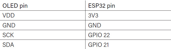
The simplest types of SSD1306-based modules are interfaced using just four pins, which is enough to drive the display using the I2C bus protocol. The connection to the display is illustrated in Figure 3, and the required connections are also set out in tabular form below.
The script shown in Listing 1 outputs a text message to the display and draws some simple graphics in the form of a box outlining it (as appears in Figure 3).
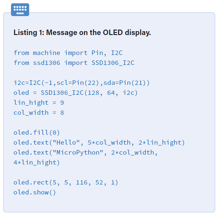
The relevant library is available as a standard package (ssd1306.py in the download archive) and can be uploaded separately to the board. The pins used for the I2C interface are declared as follows.
i2c = I2C (-1, scl = Pin (22), sda = Pin (21))
The first parameter, ‘–1’, indicates that the module that is used does not feature a reset or an interrupt pin. The number of horizontal and vertical pixels in the module is specified using the command
oled = SSD1306_I2C(128, 64, i2c)
The display is now ready for use. The function text() can be used to write information to the display buffer, and the display itself is updated using the show() method. The text() function accepts the following arguments.
• the message (a string)
• x- and y-coordinates for the text in pixel units
• optional text colour: 0 for black (not lit) and 1 for white (lit)
The show() method makes the changes visible on the display. The rect() method lets you draw a rectangle on the display. It accepts the following arguments.
• x- and y-coordinates for the bottom left-hand corner of the rectangle
• x- and y-coordinates for the top right-hand corner of the rectangle
• pixel colour: 0 for black and 1 for white
The command
oled.rect(5, 5, 116, 52, 1)
therefore conjures up a rectangular frame near the edge of the display. With just these simple commands it is possible for an application to display all sorts of information, from basic text to complex sensor readings.
Outlook
MicroPython is a modern and powerful programming language. Furthermore, its libraries allow complex projects to be realized quickly and easily. In this article, we have shown how to install a suitable IDE and create some simple applications. In the second part of this series, we will examine further aspects of MicroPython and, as a practical demonstration, give an example of how to drive a large-format LED dot-matrix display panel.
Further information about MicroPython, about the ESP32 microcontroller, and about the examples presented here can be found in the book MicroPython for Microcontrollers.
Questions or Comments?
If you have technical questions or comments about this article, you can email us at editor@elektor.com.
Want More Elektor Content About MicroPython and ESP32?
Take out an Elektor membership today and never miss an article, project, or tutorial.
Discussion (3 comments)