MIDI I/O Breakout Board – Supports DIN and TRS Connectors
At the start of 2019, some 35 years after its introduction, version 2.0 of the Musical Instrument Digital Interface, better known as MIDI, was announced. MIDI 2.0 introduces many new features, two of them being two new connectors. A new universal MIDI interface breakout board is due and here it is.
At the start of 2019, some 35 years after its introduction, version 2.0 of the Musical Instrument Digital Interface, better known as MIDI, was announced. MIDI 2.0 introduces many new features, two of them being two new connectors. A new universal MIDI interface breakout board is due and here it is.
At the time of writing this article (April 2019) the MIDI 2.0 specification has not been released yet. We will therefore not go into any detail here. What we do know is that the new standard will remain 100% compatible with MIDI 1.0.
TRS? Like "jack"?
To be honest, the new MIDI connector specification was released in the summer of 2018, and therefore is pre-MIDI 2.0. In a Letter of Agreement for Recommended Practice the Tip-Ring-Sleeve (TRS) socket/plug combination got accepted as the MIDI connector/plug, and the way to wire it to the traditional 5-way DIN connector/plug is standardized. Most people will know the TRS connectors as 'audio jack' plugs and sockets. Actually, the new connectors are just one but with two different diameters: 3.5 mm and 2.5 mm, where the latter is the recommended type. The motivation for this addition to the standard is simple and size related: the venerable DIN plug is too bulky to fit in modern, flat smartphone-like equipment.
New, new, all new!
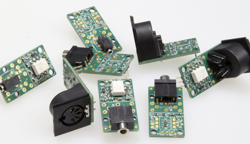
The new MIDI breakout board (BoB) we present here can be equipped with either one of the three connector types: DIN, TRS-3.5 or TRS-2.5. Furthermore, the BoB supports RF grounding and 3.3-volt signalling, and the same PCB can be configured as either a MIDI In or MIDI Out (or MIDI Thru, which is the same thing as Out).
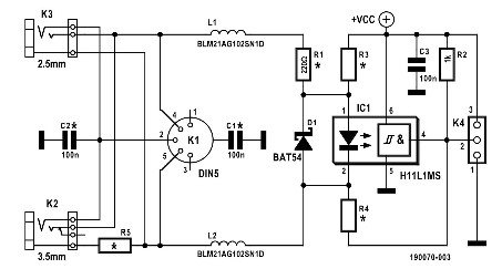
The schematic of the MIDI I/O BoB is shown in Figure 1. Due to configuration options and EMI/EMC and RF measures, there are a few more components than in a typical MIDI interface design.
Figure 1: This slightly muddled schematic of the MIDI I/O BoB is what
you get when you combine multiple circuits into one configurable circuit.
Ground loops versus EMC
The original MIDI 1.0 specification stated that in order to avoid ground loops between devices “The grounding shield connector on the MIDI jacks should not be connected to any circuit or chassis ground.” However, in 2014 this was relaxed and an optional connection between the shields of MIDI Out and MIDI Thru connectors to Ground was allowed to improve EMI/EMC performance. MIDI In connector shields may be grounded through a small capacitor, but never directly. Our MIDI I/O BoB therefore allows for these grounding options using C1 and C2. When the board is used as a MIDI In, C1 and C2 are either left off, or mounted as 100-nF (US: .1 µF) capacitors; in the case of a MIDI Out (or Thru) C1 and C2 can be 0-Ω resistors.
Avoid RF interference
Ferrite beads L1 and L2 attenuate RF interference but may be replaced by 0-Ω resistors for simplicity (depending on what you have in stock, for instance).
R3 and R4 are configuration resistors and are only required for MIDI Out (and Thru) applications. To prevent anyone from accidentally mounting them on a MIDI In module, they are placed in the same position as optocoupler IC1.
MIDI In calls for an optocoupler
The optocoupler is a fast device ensuring good signal quality and low latency between In and Thru in the case of chaining multiple MIDI devices. Diode D1 protects it against reverse-polarity signals.
R2 is the output resistor for the open-collector output on IC1. You can lower its value to improve speed slightly, but at the expense of a higher current consumption. IC1’s minimum supply voltage is 3 V, which sets the lower boundary for VCC for the MIDI In configuration (the upper extreme for IC1 is no less than 16 V).
C3 provides supply bypassing and is probably more of a good practice thing than really necessary, but hey, you never know what lengths of wires or traces people connect to K4 (keeping them as short as possible is also good practice).
Resistor R5, a 0-Ω resistor, has no function other than to provide a way to share a shield pin of K2 with a shield pin of K1 without unintendedly connecting everything to GND. It must only be mounted when K2 is mounted also.
Configuring for MIDI Out and MIDI Thru
A MIDI Out or MIDI Thru module consumes fewer parts since IC1, D1 and R2 are not needed. For these configurations R3 is a 0 Ω resistor that connects R1 to VCC. R4 is the MIDI output current limiting resistor.
The values of R1 and R4 depend on VCC. For a 5-V supply voltage, both take a value of 220 Ω; this is the traditional MIDI Out port for 5-V systems. However, for 3.3-V systems their values must be adapted as follows.
Calculations for low-voltage signalling
At its introduction the MIDI standard specified a current of 5 mA through the MIDI input’s optocoupler LED to make sure that the LED would light well. Modern optocouplers usually don’t need that much current (ours only needs 1.6 mA), but since a modern MIDI Out must still be capable of driving an vintage MIDI In, 5 mA is what is needed.
A MIDI input presents itself as a 220-Ω resistor in series with an LED; the MIDI standard assumes that this LED can have a forward voltage as high as 1.9 V. This means that the output signal level VTX must be at least:
VTX ≥ 0.005 × 220 + 1.9 = 3.0 V
Short-circuit current limiting is required, which is the function of R4. R1 and R4 together (remember that R3 = 0 Ω) will introduce a voltage drop that has to be overcome by VTX as well. Therefore
VTX – 3.0 ≥ 0.005 × (R1+R4)
With VTX = 3.3 V, we can calculate
R1 + R4 = 0.3 / 0.005 = 60 Ω
The MIDI Manufacturers Association proposes R1 = 33 Ω and R4 = 10 Ω, a total of 43 Ω, to allow for all sorts of tolerances on resistor values and supply and output voltages.
Beware of short-circuits
An easy to overlook detail is the current through R1 and R4 when the remote MIDI input is faulty and for some reason shorted to GND:
VCC / R1 = 3.3 / 33 = 0.1 A
PR1 = (0.1)2 × 33 = 330 mW
Because R1 is connected to the transmitter’s power supply which we can only assume to be powerful enough to deliver this 100 mA current, R1 must be rated for 0.5 W.
Similar reasoning holds for R4 (a 1.2-W type would be required), except that for this resistor it is assumed to be driven by an open-collector or open-drain output with a pull-up resistor. This resistor with a value of a few hundred ohms (typically) would limit the current, allowing the power rating of R4 to be relaxed to 0.25 W. Therefore, be careful when driving the 3.3-volt MIDI Out from a digital driver. This limitation does not apply to the 5-V MIDI Out.
Finally...
The above description shows that even for simple circuits there are a good many things to e-worry about, especially when trying to interconnect equipment from different origins and eras.
Final note: a complete set of nine component stuffing tables for the MIDI I/O BoB can be found at [1].
* One PCB for MIDI In, MIDI Out and MIDI Thru
* Configurable for 5-V and 3.3-V systems
* Supports DIN, 3.5-mm TRS and 2.5-mm TRS connectors
* Compliant with latest MIDI standard
Elektor Magazine has been one of the leading sources of information on electronics for engineers, designers, start-ups and companies for 65 years. Our magazine is powered by an active community of electronics engineers – from students to professionals – who are passionate about designing and sharing innovative ideas.
For them, we publish hundreds of items a year, in formats such as articles, videos, webinars, and other learning formats. Our mission is to share knowledge in every possible way and inspire readers with the latest developments within the electrical engineering sector.
Thank you for your vote!
Leave further comments in the fields below.
Thank you for your vote!
If you wish to leave a comment with your rating, please first use the login below. If not, just close this window.

Discussion (0 comments)