
Modbus Over WLAN (Part 1): Hardware and Programming
on
The Modbus protocol is widely used in the industrial sector for communication between systems and controllers. This is usually done with the tried-and-true RS485 interface and conventional copper wire. Here we present a module that allows you to use the Modbus protocol over a wireless local area network (WLAN). The module is built around an Espressif NodeMCU board fitted with an ESP8266 microcontroller. A supplementary Modbus baseboard allows you to work with 24 V signals, which is a common voltage level in the industrial environment. To demonstrate how it all works, the authors built a simple lift door controller.
Most Elektor readers are probably already familiar with the Espressif NodeMCU module and the Arduino IDE. If you fit that category, you can skip this introduction and go straight to the description of the Modbus TCP board. For everyone else, here’s what you need to know in a nutshell.
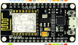
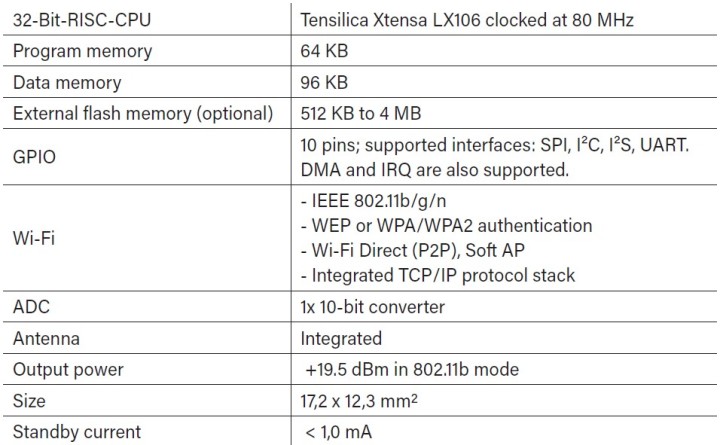
This project is built around a NodeMCU module (available in the Elektor Store). The module is fitted with an Espressif ESP8266 microcontroller, which is about the size of a postage stamp and comes with a WLAN interface. Despite its small size, it packs a lot of processing power. The key features of the ESP8266 microcontroller are summarised in Table 1.
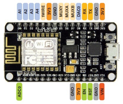
The NodeMCU board generates the supply voltage for the ESP8266 and looks after the programming interface for the microcontroller. Figure 1 shows an overview of the pinout of the NodeMCU board used in our Modbus circuit.
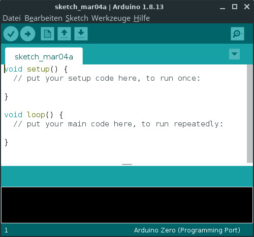
The Arduino IDE is very well suited to programming the NodeMCU board. You can download the right version of the Arduino IDE for the operating system of your computer free of charge from the Arduino website and install it according to the instructions on the site. When you run the IDE the first time, you see a window like that shown in Figure 2. The program code pane contains two predefined functions. At the top there is the setup() function, which is executed only once when the program starts and handles things like initialising the microcontroller interfaces, and at the bottom there is the loop() function, which normally contains the source code of your program.
The loop() function runs after the setup() function is completed. When the program reaches the end of the loop() function, it starts over again from the beginning. The ESP8266 manages the WLAN interface between the end and restart of the loop() function. This means you must avoid creating any infinite loops in the loop() function, as otherwise the ESP8266 will unavoidably crash. Instead, the code in the loop() function must be designed so that it can run in a cyclic fashion.
A large number of seemingly mysterious crashes of the ESP8266 are caused by the fact that the processor does not get enough CPU time to manage the WLAN interface. If there is a chance that your program code will run for an extended period, for example in large loops, you can use the yield() function or the delay() function to give the ESP8266 enough time for WLAN management.
Before you plug the NodeMCU module into the Modbus board, you must connect it to a USB port on your computer, but before that you must do a few things to get everything ready to go. The ESP8266 is not supported as standard by the Arduino IDE, so you first have to update the IDE. To do so, select File -> Preferences and enter the following URL in the Additional Board Manager URLs box:
http://arduino.esp8266.com/stable/package_esp8266com_index.json
Click OK and then select Tools -> Board ... -> to open the Boards Manager window, where you should look for ESP8266 and then install the ESP8266 Community boards.
After they are installed, under Tools -> Board > you will see the board NodeMCU 1.0 (ESP-E12 Module), and under Tools -> Port > you will see the port to which the NodeMCU board is connected (/dev/ttyUSBx in Linux or COMx in Windows).
Now you can get started with the first simple test program on the NodeMCU module. For this, open the ‘Blink’ example program under File -> Examples -> ESP8266 -> Blink. The program shown in Listing 1 blinks the LED installed on the ESP8266 board. The code that switches the LED on and off is located in the loop() function. In the setup() function the GPIO pin of the LED is configured as an output.
void setup() {
pinMode(LED_BUILTIN, OUTPUT);
}
void loop() {
digitalWrite(LED_BUILTIN, LOW);
delay(1000);
digitalWrite(LED_BUILTIN, HIGH);
delay(2000);
}
To load the program into the NodeMCU board, click the Upload icon (right-facing arrow). It takes a few seconds to transfer the program, and then the LED will start blinking. This test completes the installation and setup of the IDE.
The Modbus TCP Board
As you can see from the lead image, the NodeMCU module is mounted on the Modbus TCP board, which certainly looks very industrial. All inputs and outputs are implemented with pluggable screw terminal blocks. This simplifies assembly and allows the screw terminals to be replaced easily if they become damaged. The main task of the Modbus TCP board is to convert the 3.3 V signal level of the microcontroller inputs and outputs to the 24 V level compatible with the industrial environment. The schematic diagram in Figure 3 shows that four inputs are galvanically isolated from the microcontroller by PC814 optoisolators. These inputs are not connected directly to the microcontroller board, but instead through a 74HC151 multiplexer. This arrangement saves one GPIO pin, which allows a DHT11 sensor for measuring temperature and humidity to be incorporated in the circuit. This means that the Modbus board can also be used for simple HVAC control tasks.
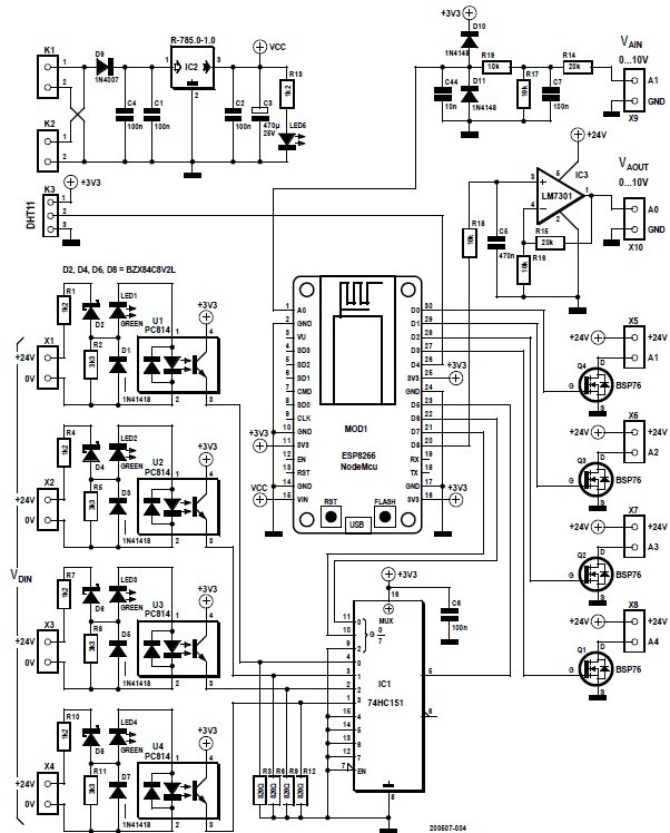
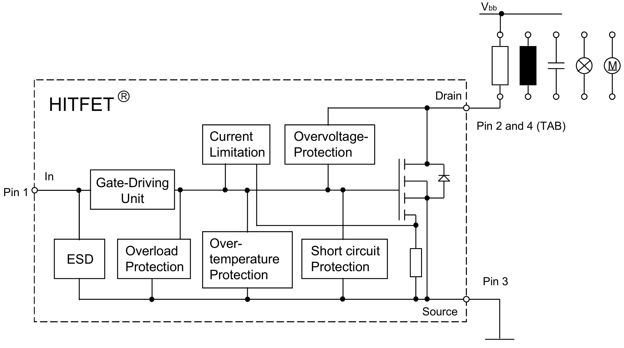
The output stages are implemented with HITFET BSP76 components (Figure 4). These are not simple power MOSFETs, but instead ICs that provide integrated protection functions, such as overvoltage protection, current limiting and overtemperature protection, for these electronic switching components. This means you can switch resistive, inductive or capacitive loads without any problems.
In addition to the digital inputs and outputs, the Modbus TCP board has an analog input and an analog output. Both analog ports operate with the industry-standard voltage range of 0 to 10 V. On the analog input the voltage divider R14/R17 reduces the input voltage to a maximum of 3.3 V. This input is not galvanically isolated, but C7, D10 and D11 provide a certain amount of protection against spikes and overvoltage. The series resistors R14 and R19 limit the input current to prevent the diodes from going up in smoke if something goes wrong on the input.
On the analog output, IC3 (an LM7301 general-purpose op-amp with rail to rail capability on both input and output) boosts the output voltage from the NodeMCU DAC. The gain of the opamp is set to 3 by resistors R15 and R16. This op-amp is powered from the 24 V supply rail.
The Recom DC/DC converter deserves special mention. It converts the 24 V supply voltage to the 5 V level required for powering the NodeMCU module. The efficiency of the DC/DC converter is well over 90%, and it is very versatile in use. For example, it can also be used to generate a negative supply voltage for opamps. It’s certainly worthwhile to have a look at the datasheet of the DC/DC converter. A 1N4007 diode is fitted directly at the 24 V input to protect the circuit against reverse voltage connection.
The Gerber files for PCB fabrication can be downloaded from github. The board is available from the author either as a bare board or fully assembled and ready to use.
Demo with a Wooden Model
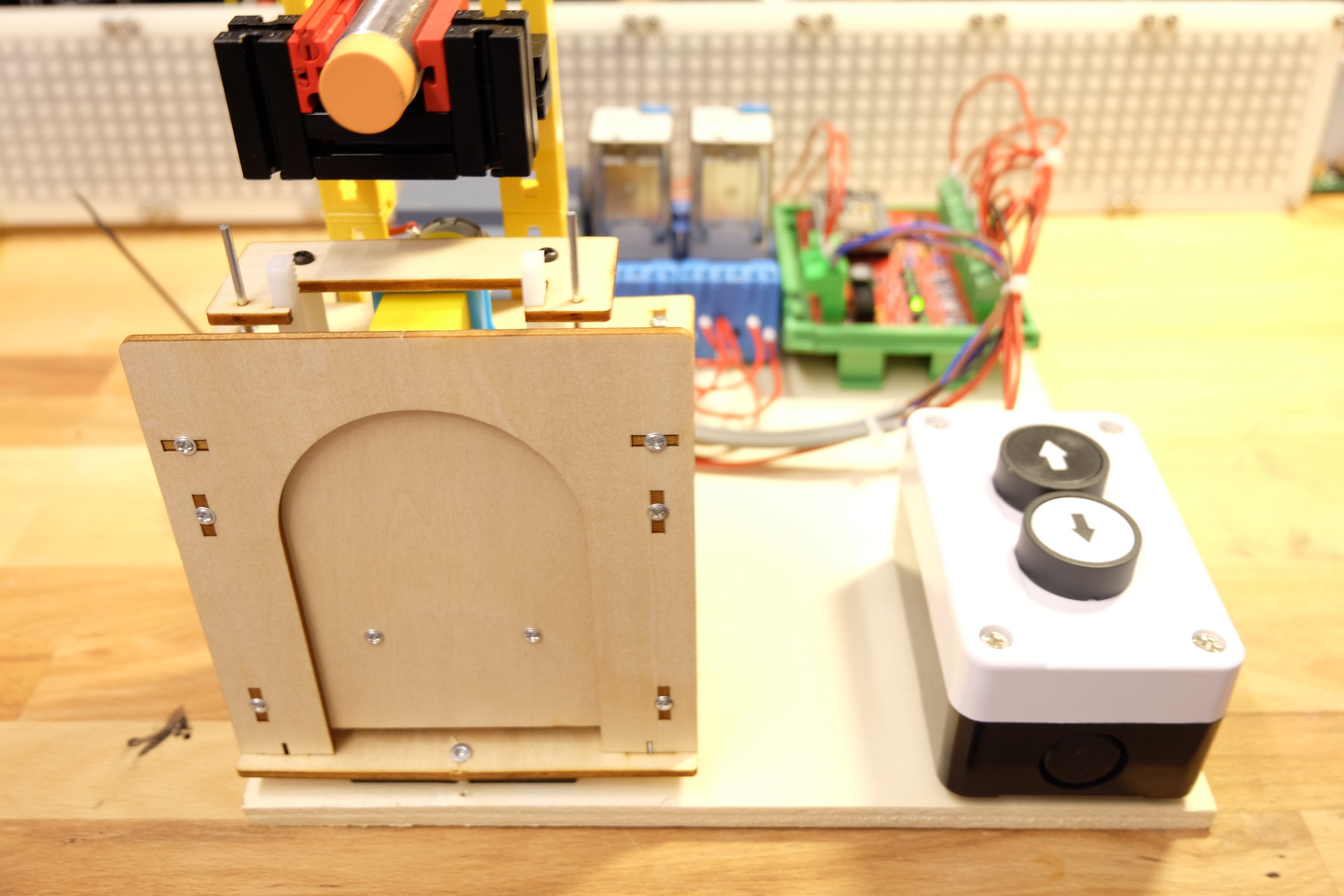
To show how the Modbus module can handle a typical industrial task, the authors used a model lift door from the well-known Chinese online store (Figure 5). The door is opened and closed by two push-buttons. The end positions of the door are detected by two capacitive proximity switches. The motor that opens and closes the door is driven by an H-bridge circuit consisting of two power relays.
The control program is shown in Listing 2. The program first defines mnemonic names for the circuit inputs and outputs. The individual I/O pins are initialised as inputs and outputs in the setup() function. This is followed by the input() and output() functions, which make it a bit easier to access the I/O pins. The main program is located the loop() function, where the outputs for driving the motor are switched on or off depending on the buttons and the limit switches. The program in the loop() function can run repetitively. If you want to see the lift door in action, simply have a look at the YouTube video [6].
#define A1 16
#define A2 5
#define A3 19
#define A4 0
#define MUXA 12
#define MUXB 13
#define MUXY 14
#define E1 0
#define E2 1
#define E3 2
#define E4 3
void setup() {
pinMode(A1, OUTPUT);
pinMode(A2, OUTPUT);
pinMode(A3, OUTPUT);
pinMode(A4, OUTPUT);
pinMode(MUXA, OUTPUT);
pinMode(MUXB, OUTPUT);
pinMode(MUXY, INPUT);
}
bool input(int i){
digitalWrite(MUXA,(i&1));
digitalWrite(MUXB,(i&2)>>1);
delay(1);
return digitalRead(MUXY);
}
void output(int i, int v){
digitalWrite(i,v);
}
void loop() {
if(input(E4)& !input(E1)){output(A1,HIGH);}
if(input(E3)& !input(E2)){output(A2,HIGH);}
if(input(E1)){output(A1,LOW);}
if(input(E2)){output(A2,LOW);}
}
Outlook
Although the working lift door controller is a nice demo, it doesn’t do justice to the true potential of the Modbus board and the WLAN module. This will be addressed in the second instalment of this article, where we will come to grips with the Modbus protocol and talk about which software you can use to communicate over the bus. We will also show you how to configure the Modbus module.
About the Authors
Josef Bernhardt developed an interest in electronics at an early age. He built his first crystal radio at the age of twelve, and carried on with other circuits. He started acquiring experience with programming in the 1980s with the Commodore VC20, and he also knows his way around assembly language programming on the 8088. He can look back on more than 30 years of electronics evolution at the University of Regensburg, where he worked in the field of electronic and software development. Using his own SMD production facility, he also implements electronic projects for customers.
Martin Mohr saw the light of day in the era of magnetic core memories and Strowger switches, enabling him to personally experience the entire evolution of modern computer technology. His fascination with everything that blinks dates back to his early youth and was further reinforced by his electronics training. After completing a course of study in informatics, he worked primarily on the development of Java applications, but the Raspberry Pi has rekindled his passion for electronics.
Discussion (6 comments)