
One-Armed Bandit: A Fun Elektor Classic!
on
Here’s another project selected from Elektor’s long history of “idea-oriented” mini articles typically found in the erstwhile Summer Circuits magazines. Back in 1984, “One-Armed Bandit” was just one of around 100 schematics, each with a few words of clarification. Almost 40 years on, we’re not just recycling this content, but actually enhancing and honoring it with a real PCB and a fancy kit from the Elektor Store. We do so all in good spirit and with feelings of light nostalgia after the glory days of 4000-series CMOS logic!
Like the “US-Style Siren” published exactly one year ago, the present plan complies with the following criteria set up for Elektor Classic projects:
- produces noise, light, movement, action, smell, havoc, “wow!” cries, irritation, or fun;
- uses inexpensive TH parts from the “old school” bin or drawer;
- is as true as possible to the original design;
- has immediate appeal to beginners and e-outsiders;
- is suitable for PCB-ing and placing on a desktop;
- is available as a complete kit for home assembly;
- is drawn in the inimitable Elektor style — meaning, stylish and educational.
With all this in mind, and more, this Elektor Classic shows a playful application of (originally) CMOS 400x series logic ICs in combination with LEDs, a highly popular combination at that time [2]. The project only imitates the core of a spinning-digit type slot machine. As such, no attempt is made to implement all the bells, whistles, flashes, and sound effects of a real slot machine — these are best experienced in an arcade hall, at your personal risk and cost! Here, we’re talking electronics and learning how things work.

The Game
To play the game, first agree on the number of rounds. Player 1 actuates the switch lever as long as desired and releases it. The LEDs then show the score, which is the sum of the 50-20-10-5 digits lit up. If the Play Again! LED lights, Player 1 has another, “free”, round. If not, it’s Player 2’s turn. The players keep tab of their scores, and the highest score wins.
Circuit Operation
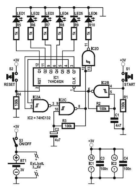
The circuit diagram shown in Figure 1 is based on a type 74HC4024 7-stage binary counter/divider, IC1. At the start of the game, it is reset by spring-loaded push-to-make switch S2, causing logic Low levels on counter outputs Q1...Q7, which in turn cause LED1...LED5 to remain off. Also, the output of NAND Schmitt trigger IC2A is logic High, switching on relaxation oscillator IC2C. The oscillator signal is inverted in IC2D and LED6 lights.
were cheap and offered great potential for hobbyists to design simple
digital electronics. The circuit diagram for a “One-Armed Bandit” shown
here (reworked from a 1984 original) is a good example of the zeitgeist.
The game is started by closing switch S1 (i.e., pulling its lever downward). This turns on oscillator IC2B which starts clocking the counter. As soon as S1 is released, IC2B ceases to oscillate and the counter stops at a random output combination for Q1...Q7. One or several of LED1...LED5 will light at that time, indicating the number of points scored by the player.
With both counter outputs Q6 and Q7 logic High, IC2C stops oscillating and LED D6 goes out, indicating “Next Player.” If Q6 and Q7 are not logic High simultaneously, D6 remains on, indicating Play Again!
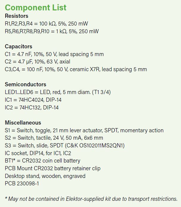
The circuit is powered by a 3-volt CR2032 type coin cell battery. Alternatively, two external 1.5-volt batteries can be connected in series using a battery holder. The current consumption depends mainly on the current limiting resistors R5...R10: the indicated values result in about 1 mA per LED. This is actually the one significant difference between H.J. Walter’s 1984 design and the 2023 incarnation seen here: today we have far more efficient LEDs and no longer need buffer transistors between the CMOS counter outputs and the “score reel” LEDs consuming 20 mA each 40 years ago. Oh, and psst… we’ve used HCMOS ICs rather than vintage 4000 CMOS — but still in DIP cases!
Building the Bandit
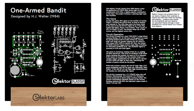
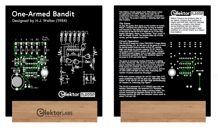
In keeping with the Elektor Classics tradition, the circuit board designed for the One-Armed Bandit has the schematic printed on the front side, and the circuit operation on the back (Figure 2). Notice the use of the renowned Elektor-style component symbols and the axial-leaded electrolytic capacitor C2 in the component mounting plan. Okay, it takes up more PCB space than its radial counterpart mostly seen today (nor even mentioning SMDs) but gives a fine touch of 1980s authenticity to the project.
Assembling this project is plain sailing as only through-hole (TH) parts are used on a spaciously designed board with a clear component overlay (Figure 3). Plus, all parts are contained in an attractively styled kit, so no need to rummage around for “ye ole” parts in dusty drawers.
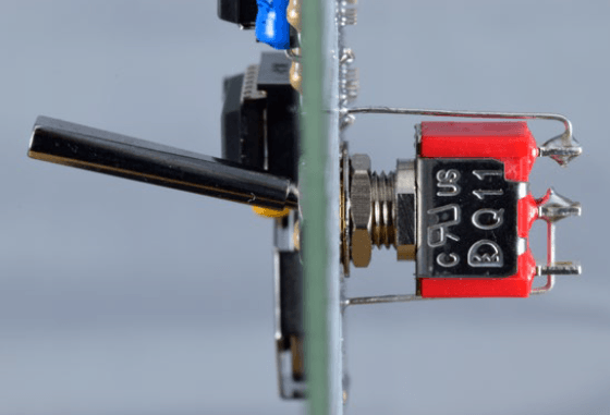
which acts as the bandit’s “arm.”
The assembled board is placed in the wooden, engraved, desktop stand included in the Elektor kit. The stand is for showcasing, really, or showing off if you like. Don’t pull that switch lever down too briskly, as the board may drop out of the stand. Use two hands, do not cheat, and be sure to limit your play time.
This article (230207-01) appears in the Elektor Circuit Special 2023. H. J. Walter developed the original project. Ton Giesberts worked on the present design.
Discussion (0 comments)