
Hands On the Parallax Propeller 2 (Part 2): Using Spin2 to Drive an LED
on
Now that you are familiar with Parallax’s Propeller 2 and its features, I want to cover the development environment and coding. Read on to learn how to use the Spin2 language to drive an LED.
Access the onboard LEDs
Let’s get started with the software environment and controlling one of the on-board LEDs. We will do our development in Windows 10 with the vendor-provided tools. At the end, a basic software setup will be in place to compile and upload code to the Propeller 2.
Parallax provided its Propeller Tool Version 2.3 Alpha including Propeller 2 support for Spin/Spin2. If assembly language is preferred, you can use PNut as development environment or do inline assembly. If you like to code in C/C++ like me, the compiler and development environments are currently not ready for prime time. There are efforts going on to improve the C/C++ compiler situation. And those can be seen at the video presentation [1] about C/C++ on the Propeller 2.
Basic development environment
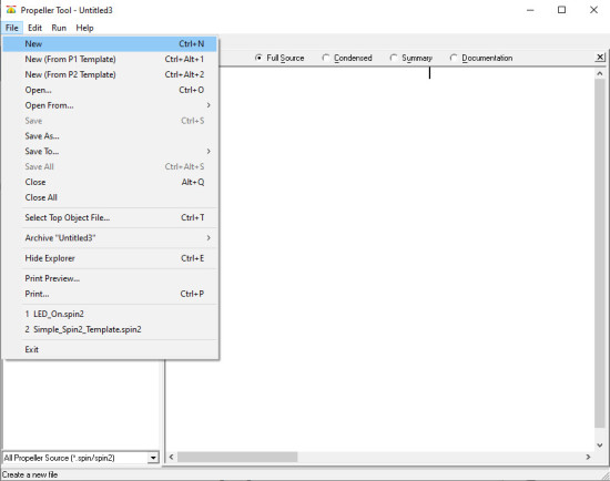
You can download the Propeller Tool 2.3 Alpha at [2]. Download the Propeller Tool 1.3.2 first and add to its program directory the Propeller Tool 2.3 Alpha executable as a second step. After the installation is done, you can start the editor and begin coding. The user interface for the tool is shown in Figure 1.
Assembler or Spin2 for coding?
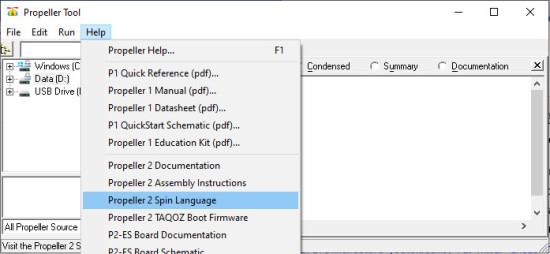
The question will be: Spin2 or Assembler for the initial code? To keep it simple, we will, for now, continue with Spin2. Spin2 is an interpreted language, like BASIC, but different. The commands and language references to Spin2 can be found using the Propeller Tool under the Help menu entry (see Figure 2).
To get started with Spin2, you can use a currently preliminary manual, but keep in mind that it is not finished yet. This will lead to the current documentation for the implemented Spin2 language on the Propeller 2 MCU.
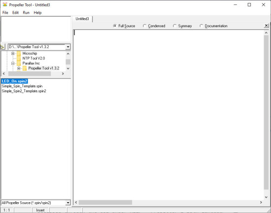
As this is interpreted code in the end, you will need approximately six instruction cycles, meaning 12 clock cycles, to execute one command. This isn’t the fastest way, in terms of clock cycles, to get things done, but Spin2 give an easier stating point than starting with assembler. As Spin2 has a more high level approach most commands hide a lot of the assembler instuctions and are more natural to use than the assembly instructions. You can create a new Spin2 project like what you can see in Figure 3.
I/O Pins
Before we continue with writing code, let’s briefly look at how the I/O pins work. We use them here as ordinary I/O pins and will offer an in-depth overview later about all their capabilities. Generally, we need to set the pin of choice as an output to drive a low or high level. On the evaluation board, you can clearly see the LEDs marked with P56 up to P63 (see Figure 4).
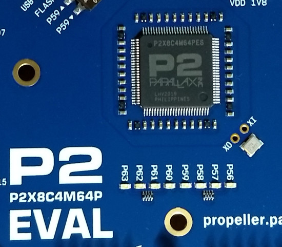
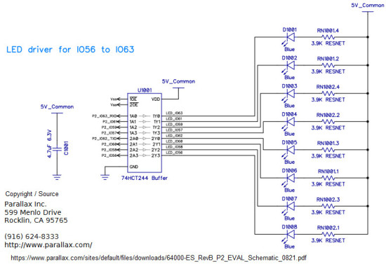
This is a group of LEDs connected to the pin 56 up to pin 63 on the Propeller 2, so we will choose the first LED56 to light it up. If you look at the schematic, it is clear that they are not connected directly to the chip but attached to a 74HCT244 octal buffer. Also notice that the LEDs are connected with their anode permanent to VCC and the I/O pin, with the buffers help will tie the cathode to ground to make them light up (see Figure 5).
Inverted LED
For the code we are going to write, this means that a driven high level at the MCU pin will turn off the LED and low level will let it light up. With this inverted logic in mind, we need to let our code drive the LED pin 56 a high state to turn it off. If we don’t do anything, the pins will be by default be an input and the octal buffer will act like the pin is driven logic high, so turning every LED connected to it off. For our Spin2 code, to light up the LED, this means we need to:
- Initialize the MCU and at least one core (cog)
- Set the pin 56 as output
- Drive pin 56 low
- Do nothing
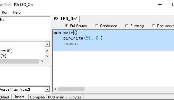
Step one, the initialisation, in this case, is done for us and we don’t need to care for this example about it. The Spin2 code itself just needs some lines of code. Our code begins with the function pub main() followed by the pinwrite() method (see Figure 6).
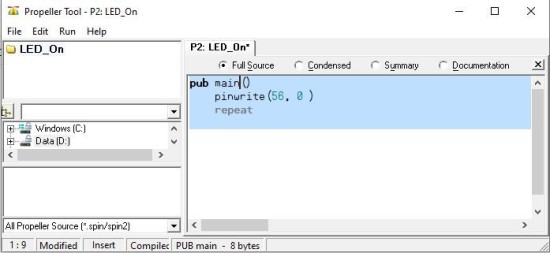
The pinwrite() is built into the Spin2 language and allows one or more pins to be set with a given value. Here we just use pin 56, which our LED is connected to, and pass for the output level a ‘0’ to turn the pin low and the LED on. The last line repeat will force the cog into an endless loop, as the code below the repeat will be executed. In this case, there is no more code forcing the cog to do nothing but keep it running. If we don’t use the repeat here, the cog will reach the code’s end and stop driving the I/O pins.
Moving code into the Propeller 2
If the code is ready, you can upload it to the Propeller 2 evaluation board and let the code execute. For this to happen, you just attach the board to one of the system’s USB ports and select from the menu Run->Compile Current->Load RAM to upload the code directly into the MCU RAM and let it execute. As the LED on pin 56 now lights up, you are done with the first kind of “Hello, world.” One question that may arise: “Can you make it blink?” Yes, this can be done. In Spin2, we have a WAITMS instruction that e.g. with WAITMS(500) will delay the execution of code for 500 ms. As we have learned that the code after REPEAT is executed over and over, the next step will be to make the LED blink. A little exercise will be to try to modify the code in a way that the LED will blink. Use the information you have gathered so far to develop and modify the code to get a blinking LED. For this exercise, we will give a sample solution later on.
As we can now drive an I/O pin, the next step is to figure out how to send serial data. Most of us are used to this debug style, especially as first or second steps on a device like an AVR. As this will involve the Smart-Pin functions, the next step will be to get familiar with those.
Want More Elektor Content Like This?
Take out an Elektor membership today and never miss an article, project, or tutorial.
Discussion (0 comments)