
PCB by CNC (Part 2): Engraving and Drilling the Pads and Vias
on
The first part of the series was about creating CAM files for printed circuit boards (PCBs) using a computer numerical control (CNC) milling machine. In this second installment, we will see how to modify the plate of our CNC2018 and then use the files to prepare our PCB, starting with engraving and then drilling the pads and vias.
Modification of the CNC2018 Plate
The CNC used for our tests has a PVC plate with a series of grooves for attaching the PCB, which were not always convenient to use; therefore, we thought of making a modification to improve this aspect. We describe it here for the benefit of those who already own it or decide to purchase it.
Let’s look at the materials needed:
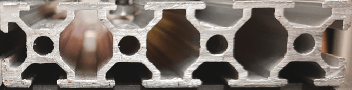
- Aluminum panel with regular grooves set up for M5 nuts (Figure 1), to cover a maximum area of 24 × 18 cm. For our needs, a surface of 20 × 16 cm is more than fine, which we obtained with two 20 × 8 cm panels side by side, which can be purchased separately or in the form of a single 40 × 8 cm panel that must then be cut into two equal parts. In the latter case, the expense is less, but you need to have the necessary cutting equipment;
- 4 × M5 nuts per profile (8 more will be needed for supports) with the corresponding bolts and washers.
The simple steps to follow:
- Pair and center the two panels on the top of the original plate and temporarily secure them with very strong adhesive tape. It is important that the two panels are perfectly aligned and in contact with each other, and the open edges should be oriented along the X-axis of the plate, so that the closed edge is seen in front.
- Turn the CNC upside down and thread the 4 nuts into the grooves so that they are visible through the slots in the PVC plate and are symmetrical.
- Mark the points with a marker, both on the panels and on the bottom of the PVC plate.
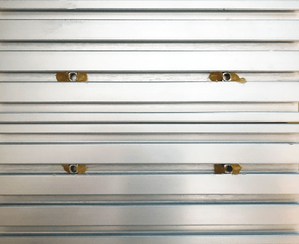
- Remove the panels and secure the nuts with hot glue (Figure 2).
- Secure the panels with 4 bolts and washers (Figure 3).
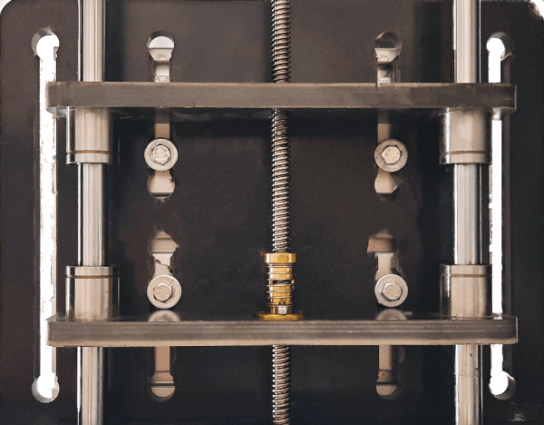
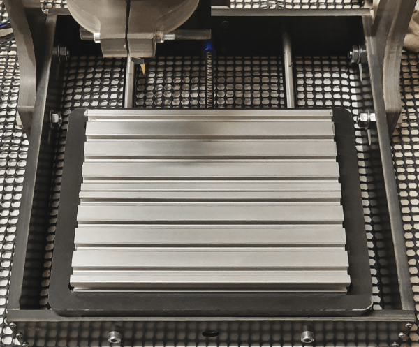
If everything has been done according to our instructions, the result will be as seen in Figure 4. This modification results in the loss of about 2 cm in height, but the Z-axis travel of this CNC is sufficient for PCB machining.
To complete the job and make the most of our new plate, we now need PCB mounting brackets, which we made by 3D printing. You will find the STL files here. These supports are designed to make the most of the aluminum profile grooves, adapting to virtually any PCB size, and spacing it from the bed to facilitate drilling. The “L” system with screws and nuts (embedded in the bracket) allows for a perfect PCB fixation, which is critical for engraving purposes (Figure 5). The holders were designed for M6-type screws/bolts, but they are safely usable with the M5 types.
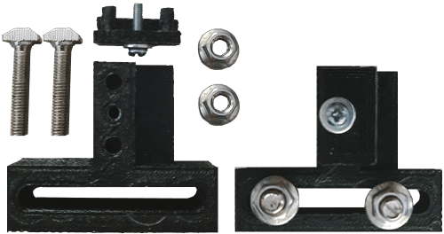
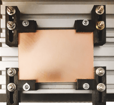
We will need to print two regular and two mirrored holders, as well as the four “L” components for PCB fixation. As seen clearly in the photo, each of the 4 supports requires two M5 profile screws, approximately 25 mm long, two nuts with an integrated washer (a separate pair is also fine), and a small M3 screw with a washer and nut (to be inserted in the specific groove of the support). In Figure 6 we show the final result with the PCB ready for the next steps. With this type of holder, the minimum size of a copper-plated board can be as small as 5 × 3.5 cm.
The Copper-Plated Board for the PCB
Depending on the PCB dimensions obtained from the design, a single-sided copper-plated board should be prepared. In our case, it needs to be slightly larger than the design, by about 1 cm on each side, to avoid the cutter hitting the supports and getting damaged. The board should be fixed to the supports with the side to be engraved facing upwards. Please note: Sometimes copper-plated PCBs, if they are not of high quality, may have thickened edges due to factory cutting. This could cause issues during engraving since it would prevent a solid attachment to the supports, so it is necessary to file all edges until these unwanted parts are removed on both sides.
We remind you of the two free programs available for download, FlatCAM and Candle. However, it is always advisable to refer to their latest versions (not the beta ones, though). The use of FlatCAM, with the generation of related files, has been described in the previous installment. Now we will delve into Candle, instead.
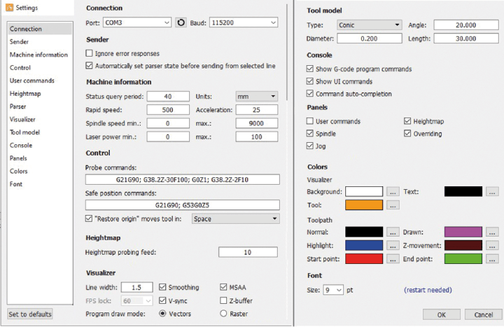
No installations are needed. The unzipped folder can be placed wherever you prefer. Just open it and run the Candle.exe file. The first thing to do is set up the program correctly. With the controller connected to the PC’s USB port, select the corresponding COM port in the Service-Settings menu and then configure the fields of interest, as shown in the image in Figure 7. Finally, confirm everything with OK.
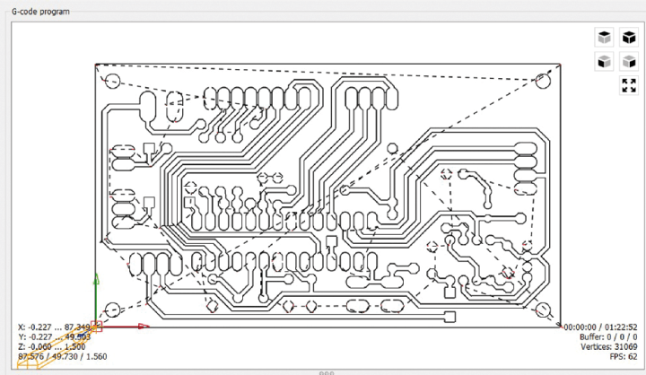
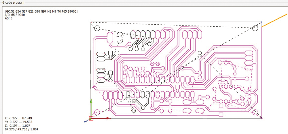
If the selected port is the correct one, in the right part of the mask the Status field will show the Idle value. If instead you will read Opened, then you have to go back to the settings and change the port, selecting it among the available ones. Open the CAM file Name_PCB.nc (“Name” is the one you gave to the file you created with FlatCAM). In the middle section of the mask, you will see the PCB tracks and pads, with some dotted lines representing the path the graver will take during engraving (Figure 8). Let’s look at an overview of the fields and buttons, located on the right side of the mask, and which we have numbered in Figure 9.
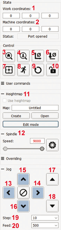
1. Works Coordinates: the three X-Y-Z fields are continually updated during machining.
2. Machine Coordinates: the three X-Y-Z fields contain the absolute coordinates of the machine. When a job starts with origins at 0,0,0, the three fields coincide with the work coordinates.
3. Home: starts the homing cycle procedure with the $H command. It should be used and works correctly only if the CNC is equipped with limit switches.
4. Z-probe: is used to find the Z-zero, i.e., the point of contact between the tip of the burin and the surface of the copper layer. It should be used with the probe correctly connected; otherwise, the probe tip will irreparably break.
5. Zero XY: is used to zero the working coordinates X and Y at the moment the graver is placed at the point of origin of machining.
6. Zero Z: serves to reset the Z work coordinate when the probe touches the surface of the copper-clad board at the origin point of the work.
7. Restore Origin: restores the working coordinates with the machine coordinate values, using the G92 command.
If in the Candle settings you enable the Restore origin box (recommended option!) by clicking on the button, the CNC will start up and, according to the set value:
Plane: the spindle moves to XY zero, moving only horizontally.
Space: the spindle moves to zero XYZ, moving horizontally and vertically.
8. Safe position: brings the spindle to a safe position along the Z-axis, keeping the tool away from the copper plate. The position is determined by the value set in the Safe Position Commands field. In our case, the final Z5 means that the spindle is brought 5 mm away from the PCB. This point is reached regardless of the initial position of the spindle, so it is raised or lowered to stop exactly 5 mm from the surface of the copper plate.
9. Reset: resets the CNC with the Ctrl+X command.
10. Unlock: unlocks the CNC from the alarm condition with the $X command.
11. Heightmap: section reserved for mapping the copper surface.
12. Spindle: section for controlling the spindle motor. It displays the set value using the slider below, with a range from 0 to the maximum limit entered in the settings. The maximum value should match the one entered in FlatCAM. The button next to the slider is used to start/stop the spindle motor.
13. X-: moves the spindle to the left.
14. X+: moves the spindle to the right.
15. Y+: moves the plate to the front of the CNC.
16. Y-: moves the plate to the back of the CNC.
17. Z+: moves the spindle upward.
18. Z-: moves the spindle downward.
19. Step: axis displacement in mm.
20. Feed: axis displacement speed in mm/min.
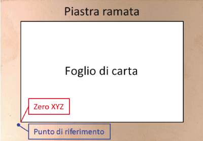
The XY zero is the point where you want to start engraving the PCB design. To choose the zero, you need to virtually position the PCB on the copper-plated surface. Here is an example: if this surface is 10 × 7 cm and the PCB design is 8 × 5 cm, it’s a good idea to center the PCB, leaving about 1 cm of space from each edge of the board. To assist you, you can cut a piece of paper with the exact dimensions of the PCB and temporarily place it on the board, centering it as best as you can. You can then mark a point near the corner that will become the zero of the work area. However, be cautious not to mark exactly on the corner, as the ink could hinder electrical contact between the tool and the copper of the board, obstructing the operation of the Z Probe (Figure 10).
Using the X/Y buttons you have to position the spindle more or less at the mark made with the marker, then you will need to click on the Zero XY button to set a temporary XY zero. It doesn’t need to be extremely precise at this point.
The “Probe Z” Probe
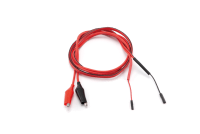
Before inserting the burin, let’s do a test with the Probe Z probe, which is quite simple to set up. You’ll need a standard bipolar cable. At one end, connect a 2-pin header plug, and at the other end, attach two alligator clips (Figure 11). The header terminal should be inserted into the specific pair of pins on the external controller connector. In the case of your CNC controller, the pin is labeled PB; in other cases, you may find it marked as A5. The initial test should be done without a burin because, in case of a malfunction, it could break upon contact with the copper-plated board.
You have to bring the spindle to the highest possible point, using the Z+ button. Then set a value of Step = 20 (manually enter this value) and then click on the Z- button. As soon as the spindle starts moving downward, briefly short-circuit the two alligator clips of the Probe. If the spindle completes its 20 mm movement without responding to the short-circuit between the two clips, it means something is wrong, and you need to address the issue; otherwise, there’s no point in continuing with the Probe.
On the other hand, if the spindle quickly moves downward and stops on its own at a certain point, this indicates that the controller detects the contact between the two clips. This behavior might suggest a malfunction with the Probe, but this won’t be the case with the actual test following our instructions.
If all good, you can insert the 0.2 mm burin into the spindle’s chuck. With the tool raised above the board’s surface, start the motor by clicking the relevant button and observe the tip. If the tool is not inserted and secured properly, you’ll feel like you’re seeing a double tip. If you don’t resolve this issue, the engraving result will be confusing, to say the least!
Set the Step to 1 so that you have movements of only one millimeter. Lower the spindle so that the point of the burin is brought up to about a couple of millimeters from the copper plate, exactly on the point chosen as the XY zero, which does not have to coincide with the marker sign. Now we need to connect the Probe’s tweezers correctly: one should be hooked directly to the graver and the other to the copper plate, at a point outside the work area to be engraved (the usual piece of paper will be useful). This is important, otherwise during mapping the graver might bump into the tweezer, damaging it.
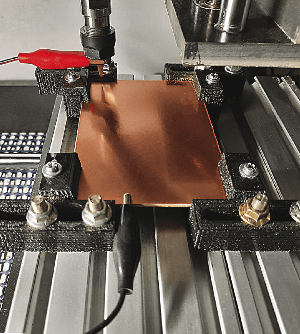
In Figure 12, we have taken a picture of the CNC during the Z-zero search phase to demonstrate how the two clips should be connected.
The last action is to insert (under the main mask):
- In the Probe grid Zt field, the value 1.00.
- In the Probe grid Zb field, the value -2.00.
At this point, you can begin the procedure for setting the Z-zero. This operation is critical; a standard plated board normally has a copper thickness of about 0.035 millimeters (35 microns), in CAM we have set a depth of 0.06 mm. So if you don’t start exactly from the contact between burin and surface, you will easily get bad results.
Just by clicking on the Z-probe button, the burin will be slowly lowered. It may appear not to be moving due to its very slow speed, but you can confirm the progress by observing the decrease in the Z coordinate values in the working coordinates field. The instant the tip of the burin touches the coppered surface, the burin is raised by 1 mm and then lowered again, stopping at the contact with the PCB.
If an alarm occurs during the descent, it means that the tool’s tip exceeded 2 mm away from the PCB. In this case, click the Unlock button, then the Zero Z button, and once again the Z-probe button. If the burin stops in contact with the copper plate, without error, the procedure was successful, so you can click on the Zero-Z button and then on Zero-XY. If you have followed these instructions carefully, the value 0 should now appear in the three fields of Works coordinates.
The next step is to match the Works coordinates with the absolute coordinates of the machine. This will come in handy later, especially in case you have to stop working. We need to perform the following operations in sequence:
- Close Candle.
- Turn off the power supply of the CNC controller, no need to disconnect the USB.
- After a few seconds, reopen Candle and then turn the power supply back on.
- Click on Restore origin.
- Click on Zero Z and Zero XY.
- Click on Restore origin again.
Now, hovering the mouse arrow over this button will bring up a small box showing the values 0, 0, 0. If this doesn’t happen, repeat the entire software sequence (not the Z zero sequence).
Mapping the Copper Layer
Now, you can open the CAM file of the PCB. The drawing will appear in the main Candle window. Mapping is a crucial step for achieving a perfect engraving of the copper layer of the board. Typically, any deformations in the board can cause its surface to be not perfectly level. As a result, in areas lower than the Z zero, the engraving might not occur, while in higher areas, very deep grooves might be produced.
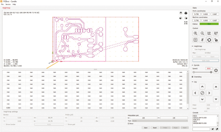
By creating a map of the copper-clad board, the software will compensate for these irregularities during the engraving process. In the Heightmap section, click on the Create button. Below the PCB area, the mapping area will open (Figure 13):
- Activate the three checkboxes labeled Show... .
- Click on Auto so that the red box coincides with the edges of the PCB drawing. This way, its real dimensions will be displayed beneath it.
- Enter an integer value in the Probe grid X field, approximately double the width of the PCB design (in centimeters). For example, if the PCB is 8 cm wide, you can use a value of 16. This value sets the mapping for the X-axis with readings approximately every 0.5 cm.
- Enter an integer value into the Probe grid Y field, approximately double the depth of the PCB design (in centimeters). For example, if the PCB is 5 cm deep, you can use a value of 10. This value sets the mapping for the Y-axis with readings approximately every 0.5 cm.
- Check that the Probe grid Zt field is set to 1.00
- Check that the Probe grid Zb field is set to -2.00
- Enter an integer value between 50 and 200 in the Interpolation grid X and Y fields. This value sets the interpolation between adjacent mapping points. We used 100, but 50 is probably more than fine.
We are now ready to begin the mapping operation. The Probe Z must still be connected between the burin and the copper plate. Click on the Probe button (not to be confused with Z-Probe), located at the base of the mask. The graver will make an initial check of the XYZ zero and then begin checking the points set up for mapping. At each point, the corresponding grid box will be filled. When finished, a colored map will be displayed on the screen.
Since the graver will stop at the position of the last point on the map, click on Restore origin to return the graver to the XYZ zero position. Let’s see how to interpret the colorations, which represent the leveling deviation from the Z zero (Figure 14).
Negative values indicate that the graver has descended lower than the Z zero at that point. Positive values indicate that the graver has touched the plate before reaching the Z zero. Green areas indicate a level very close to Z zero. Light blue areas indicate a slightly greater depth, while dark blue areas indicate a more consistent depth. Yellow areas indicate a slightly shallower depth than Z zero, while red areas indicate a more consistent shallower depth than Z zero.
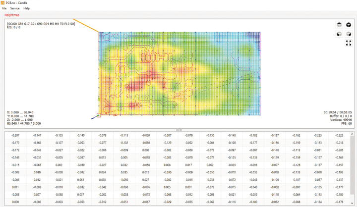
Of course, you don’t need to check these correspondences; you should also consider the effect of interpolation. However, it’s all automatic. Click on Create, then click on YES at the eventual confirmation prompt, and name the file something like Name.map, choosing the same path as the CAM files.
Click on Edit mode to remove the Heightmap mask and the PCB reappears. Activate the Use Heightmap box, click Open and open the .map file you just created. The software will recalculate all the XYZ coordinates based on the map.
The last operation to be done is the repetition of the Z zero, again through the use of Probe Z; this operation should not be neglected as it often happens that at the end of the mapping the Z zero is slightly modified, which would negatively affect the engraving. Immediately afterward, the Probe Z probe should be disconnected from the controller and the tweezers unhooked, setting the lead aside.
PCB Etching
Before starting this operation, we recommend having emulsifiable lubricating and cooling oil for mechanical tools. Typically, this is prepared as a 1% mixture in regular tap water and can be put into a spray container for easy dispensing. An initial spray must be made on the Z zero area.
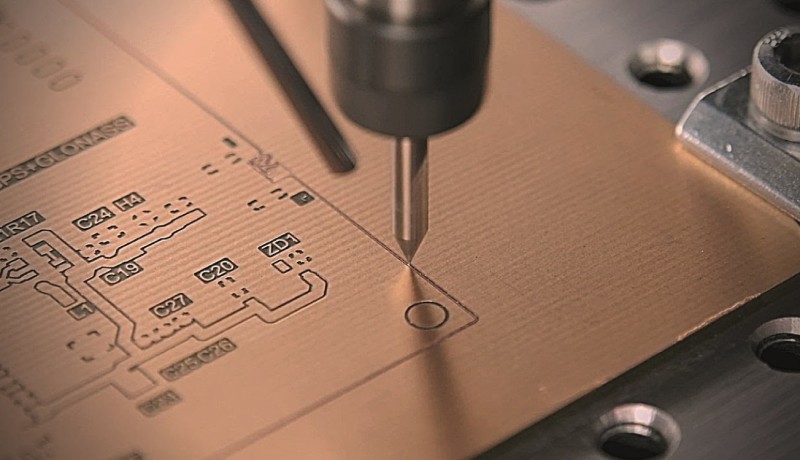
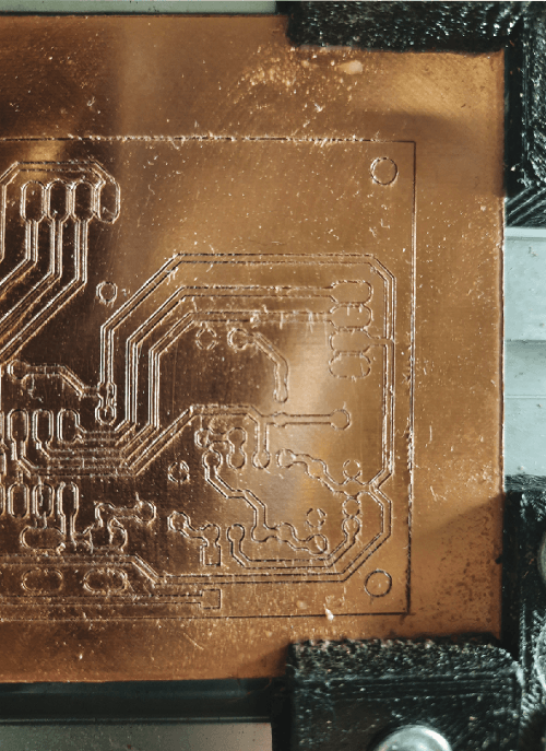
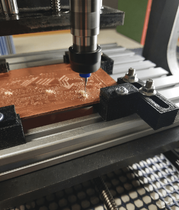
At this point, it is convenient to raise the burin 5-10 mm above the board and click on the SEND button. The spindle motor will start, and the burin will reach the point where engraving should begin. You should follow the engraving while applying the oil-water mixture to the copper, as this helps the burin’s performance, prevents overheating and damage, and improves the quality of the copper engraving. (Figure 15).
However, one must keep a safe distance from the burin because contact would be extremely dangerous!
The Candle graphically shows the etching process. The graver is represented by a pointer that shows where it is. Furthermore, the PCB traces change color as they are etched. It’s worth noting that the CNC machine typically makes a double pass for larger tracks and pads, with the second pass being slightly deeper. Thus, the first pass might not be deep enough in some areas (Figure 16). In case of problems, you can click the ABORT button to immediately stop the operation.
At this point you can apply the necessary corrections and start the engraving all over again using the Send button. However, you must not close and reopen Candle or disconnect the cable, otherwise you may lose the zero XY references. Under these conditions, you can resume engraving with confidence that the tool will follow precisely the previous traces.
Please note: Each time you run Abort, before relaunching the engraving procedure, you must reload the Heightmap file and repeat the zero Z procedure.
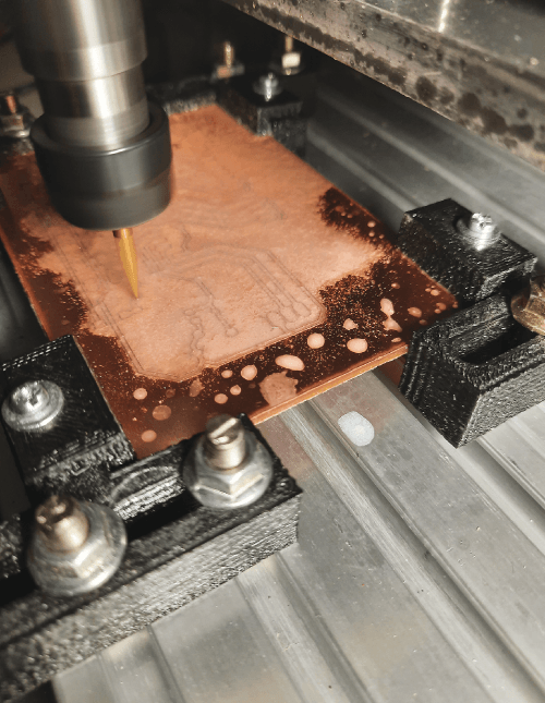
Once the engraving process is complete, to proceed with the drilling step, you must not exit the Candle or disconnect the USB, to maintain the XY references. The surface of the board will be full of copper residue mixed with emulsifiable oil. One can resort to the XYZ movement buttons to easily access the board for cleaning without disassembling it from the plate. This can be done with a brush or a piece of cloth. No need to worry about the new coordinates, drilling will automatically start from zero XY.
Many factors contribute to the quality of a PCB’s manufacturing. Sometimes it turns out perfectly, but more often, the surface may appear rough, which can be indicative of excessive engraving depth or an imperfect tool condition. Furthermore, one must consider the residual “dough” between oil and milled material, so the PCB may look as in Figure 17.
Drilling
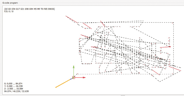
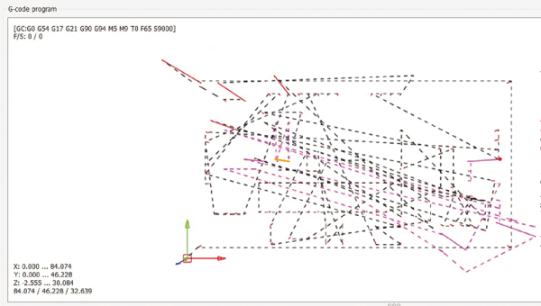
Without exiting Candle, to maintain the zero XY settings, open the Name_FORI.nc file. The mask will show up as a series of dashed lines, representing the path the CNC will take during the drilling process (Figure 18).
Please note: It is important to turn on the Autoscroll box in the lower-left corner; otherwise you will not see the software messages for changing drills.
You should re-zero the Z axis, since the drill bits are longer than the engraving tools. However, you can’t use the Probe Z because the drill bit may not guarantee electrical contact with the PCB’s copper-clad surface, and it could break.
Raise the spindle and replace the burin with a drill bit, ensuring that it’s inserted until it touches the spindle’s colored reference ring, and tighten it securely. CNC-specific drills usually feature a colored ring that is used to ensure the same protrusion from the spindle. Unfortunately, it can happen that this ring (which is fixed) is in a different position among the different sizes, causing one part of the drilling tool to protrude more or less than others.
It may therefore happen that, once the Z zero calibration has been made with a drill, if we replace it with another one that protrudes more, it might damage the PCB during movements between holes and could even break. The problem doesn’t occur if the drill bit protrudes less because the value of depth (Cut Z) that we have entered in the FlatCAM can compensate significantly for any differences. Therefore, it’s a good idea to take all the drill bits intended for the PCB and use the longest one for calibrating the Z zero.
Obviously, the part of interest is the helical part below the ring and not the part above. If, on the other hand, you have drills without the ring, then it is best to determine how far they should protrude from the spindle and mark the point on all of them with a permanent marker.

In Figure 19 we have the two types of drill bit sets. Move outside the PCB area and start the rotation of the spindle motor with the Z button. Lower the bit to come within about 1 mm of the PCB, set the Step value to “0.1,” then continue until you feel contact with the copper layer. Now click on the Zero Z button.
Raise the tip a couple of centimeters and then click Send. The program will instantly pause with an error message, and a highlighted line will appear in the command section with the required bit size for the first set of holes (Figure 20).
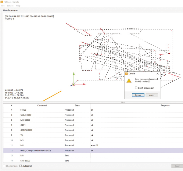
If you’ve calibrated with this specific drill bit, there’s no need to replace it. However, if the requested value doesn’t correspond to a standard size, you should use the nearest available size. In the example from Figure 20, a 0.61 mm drill bit is required. You can use the 0.6 mm one just fine. When the substitution is done, click on the Pause button and thus start drilling. The CNC will drive the three motors, bring the drill to the XYZ zero position, and proceed to the first hole, following the path indicated by the dashed lines. Similar to engraving, the dashed lines will change color as drilling progresses (Figure 21).
You should not worry about cleaning the PCB while drilling. In fact, we recommend that you avoid doing any kind of operation because it is very dangerous to get your hands or a tool near a drill bit, which, no matter how small, could do serious damage! If there is a problem (for example, if you break a drill bit) you can click, at any instant, on the ABORT button to immediately cancel the operation.
At this point, you can remove the problem and start drilling again using the Send button. However, you must not close and reopen Candle or disconnect the cable; otherwise you may lose the XY zero references. Only under these conditions, you will be able to start drilling again, having confidence that the drill bits will pass exactly over the previous holes.
Please note: If you find yourself repeating the drilling from the beginning, you can avoid inserting the bits that have already completed their cycle. The CNC will still make the movements without the cutting tool. When you reach the request for the drill bit that broke, you can insert it.
End of Operations
When the drilling operations are finished, raise the spindle and remove the drill bit, then remove the PCB from the plate. The PCB should be cleaned initially with a hard bristle brush, then it can be put under flowing water. Next, dry it, preferably with an air jet. If, as in our case, the surface is not perfectly smooth, it must be treated with very fine sandpaper, again under running water, until all roughness disappears.
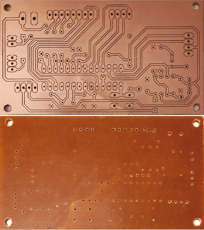
In Figure 23 you can observe the quality of the finished product on both sides, which truly has nothing to envy compared to work done at a service provider, except, of course, for the lack of metallization and solder mask. However, in the end, it’s still a prototype!
A final note concerns the offline controller we discussed in the article on the CNC controller. Keep in mind that it is fine for the engraving procedure, but not for the drilling procedure. This is because, excluding PC control, it wouldn’t allow for changing drill bits, and the tool change message would result in an error.
Editor’s notes: Interested in CNC and PCBs? This project (PCB by CNC) originally appeared in Elettronica IN.
Discussion (1 comment)