
Raspberry Pi Pico Essentials
on
This installment of Elektor Books presents roughly half a chapter excerpted from Dogan Ibrahim's book Raspberry Pi Pico Essentials, which was published by Elektor in March 2021 and is now a bestseller. At that time, it was the first third-party book with tried-and-tested, real-life dealings with the RP2040 microcontroller onboard the Raspberry Pi Pico module, complete with software to go. Is the Pico as accessible as it is claimed to be, and does it live up to its expectations of being a "drop-in" controller board? Let's find out. In this article (originally about half of book chapter 10, Ed.), we shall be developing a project using a Wi-Fi link to establish communication between the Raspberry Pi Pico and a smartphone.
Controlling an LED from a Smartphone Using Wi-Fi
Description: In this project, we will be sending commands over the Wi-Fi link from a mobile phone to control an LED (the LED can be replaced with a relay, for example, to control a piece of equipment) connected to the Raspberry Pi Pico. Commands must be terminated with a Return (CR/LF or ‘newline’). Valid commands include:
| LON | Turn LED ON |
| LOFF | Turn LED OFF |
Aim: The aim of this project is to showcase the use of the Wi-Fi connectivity on the Raspberry Pi Pico.
Pico Wi-Fi Connectivity: The Raspberry Pi Pico has no built-in Wi-Fi module and as such, it cannot be connected to a Wi-Fi network without interfacing it to an external Wi-Fi module. Perhaps the easiest and the cheapest way of providing Wi-Fi capability to the Pico is by using an ESP-01 processor board. This is a tiny board (see Figure 1), measuring only 2.7 cm × 1.2 cm, and based on the ESP8266 processor chip, and costing around US$ 4 or €4-5. The ESP-01 has the following motivating features:
- Operating voltage: +3.3 V
- Interface: using simple AT commands over serial port/UART
- Integrated TCP/IP protocol stack
- 802.11 b/g/n
- No external components required
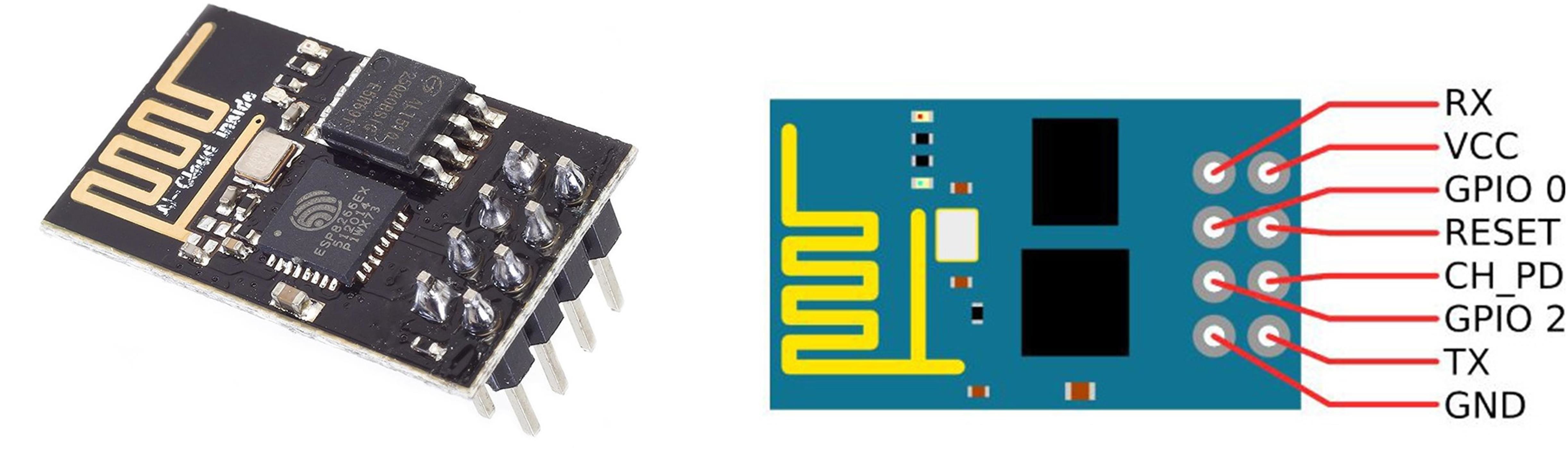
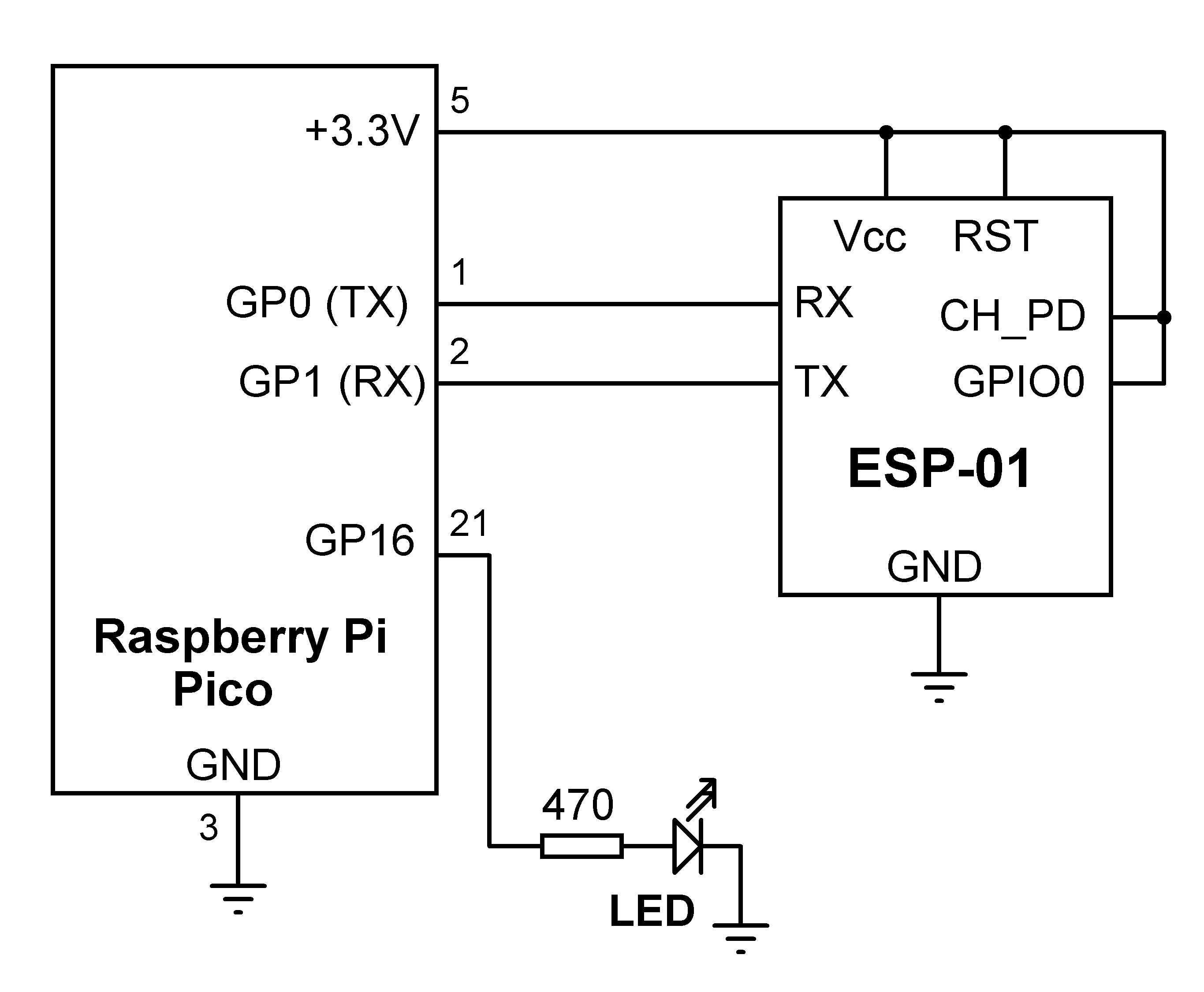
The ESP-01 communicates with the host processor through its TX and RX serial port pin. It is an 8-pin board with pin names as follows:

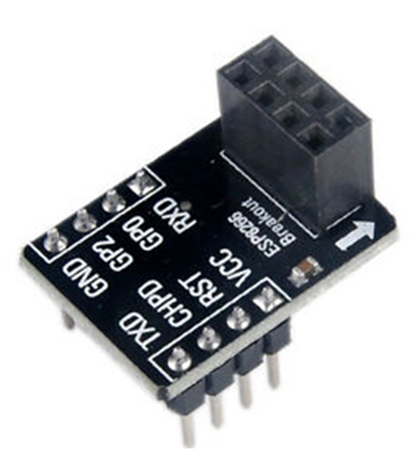
The ESP-01’s pins are not standard breadboard-compatible, so an adaptor is required if the board is to be attached to a breadboard (see Figure 2).
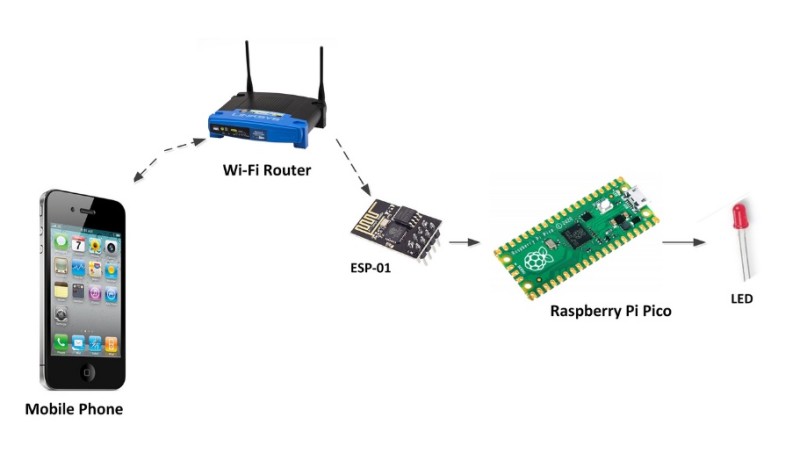
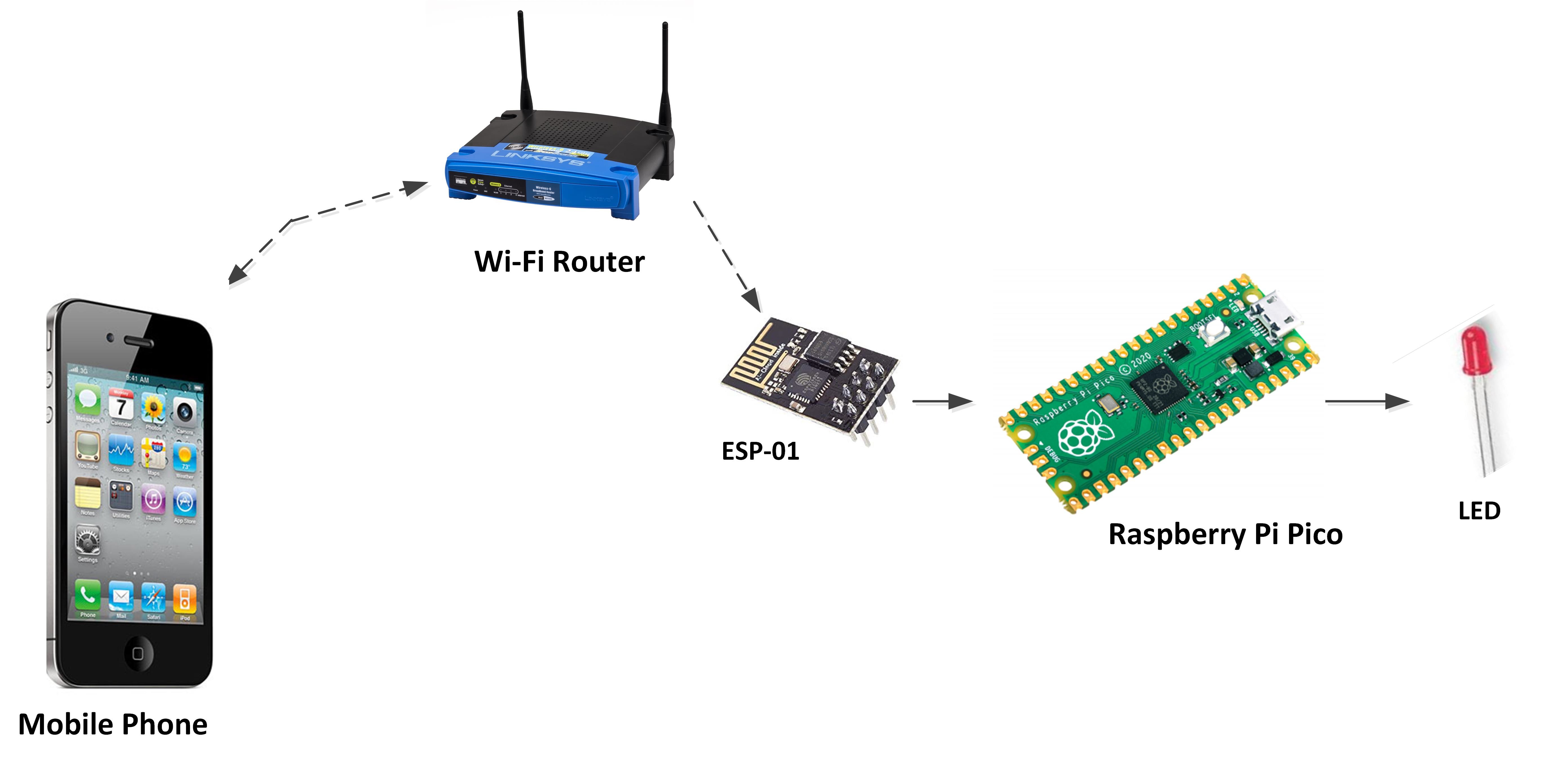
Block Diagram: Figure 3 shows the project block diagram.
Program Listing: Listing 1 shows the program listing (program: Picowifi). It is included in the cumulative programs file found under Downloads on the Elektor web page for the book [1]. Inside the setup routine serial communication speed is set to 115200 which is the default Baud rate for ESP-01, and the LED is configured as an output and turned OFF. Function ConnectToWiFi is called to connect to the local Wi-Fi router. AT-style commands are used to configure the ESP-01 to connect to the Wi-Fi router.
Listing 1: Python program to control an ESP-01 as Wi-fi-module
# USING WI-FI
# ===========
#
# In this project a ESP-01 chip is connected to the Raspberry
# Pi Pico. This chip is used to connect the Pico to the Wi-Fi
#
# Author: Dogan Ibrahim
# File : Picowifi.py
# Date : February 2021
#------------------------------------------------------------
from machine import Pin, UART
import utime
uart = UART(0, baudrate=115200,rx=Pin(1),tx=Pin(0))
LED = Pin(16, Pin.OUT)
LED.value(0)
#
# Send AT commands to ESP-01 to connect to local WI-Fi
#
def ConnectToWiFi():
uart.write("AT+RST\r\n")
utime.sleep(5)
uart.write("AT+CWMODE=1\r\n")
utime.sleep(1)
uart.write(’’’AT+CWJAP="BTHomeSpot-XNH","49345xyzpq"\r\n’’’)
utime.sleep(5)
uart.write("AT+CPIMUX=0\r\n")
utime.sleep(3)
uart.write(’’’AT+CIPSTART="UDP","0.0.0.0",5000,5000,2\r\n’’’)
utime.sleep(3)
ConnectToWiFi()
#
# Main program loop
#
while True:
buf = uart.readline() # Read data
dat = buf.decode(’UTF-8’) # Decode
n = dat.find("LON") # Includes LON?
if n > 0:
LED.value(1) # LED ON
n = dat.find("LOFF") # Includes OFF?
if n > 0:
LED.value(0) # LED OFF
The remainder of the program runs in an endless loop formed using a while statement. Inside this loop, data is received from the smart mobile phone, and the LED is controlled accordingly. Commands LON and LOFF turn the LED ON and OFF, respectively. Data packets are received from the smartphone using the readline function. Function find looks for a substring in a string and returns a non-zero value if the substring is found. The find function is used because the data received from the mobile device is in the following format: +ID0,n: data (e.g. +ID0,3:LON) where 0 is the link ID and n is the number of characters received. Using the function find we can easily search for the strings LON or LOFF in the received data packet.
Function ConnectToWiFi sends the following commands to the ESP-01 to connect to the Wi-Fi network:
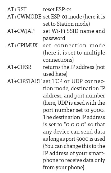
Notice that small delays are used after each command. Command AT+CWJAP requires a longer delay. The program can easily be modified such that the delays can be removed and the responses from the ESP-01 can be checked. This way, as soon as the correct response is received, the program can continue. You may have to hardware-reset the ESP-01 by powering it down and up again before you run the program.
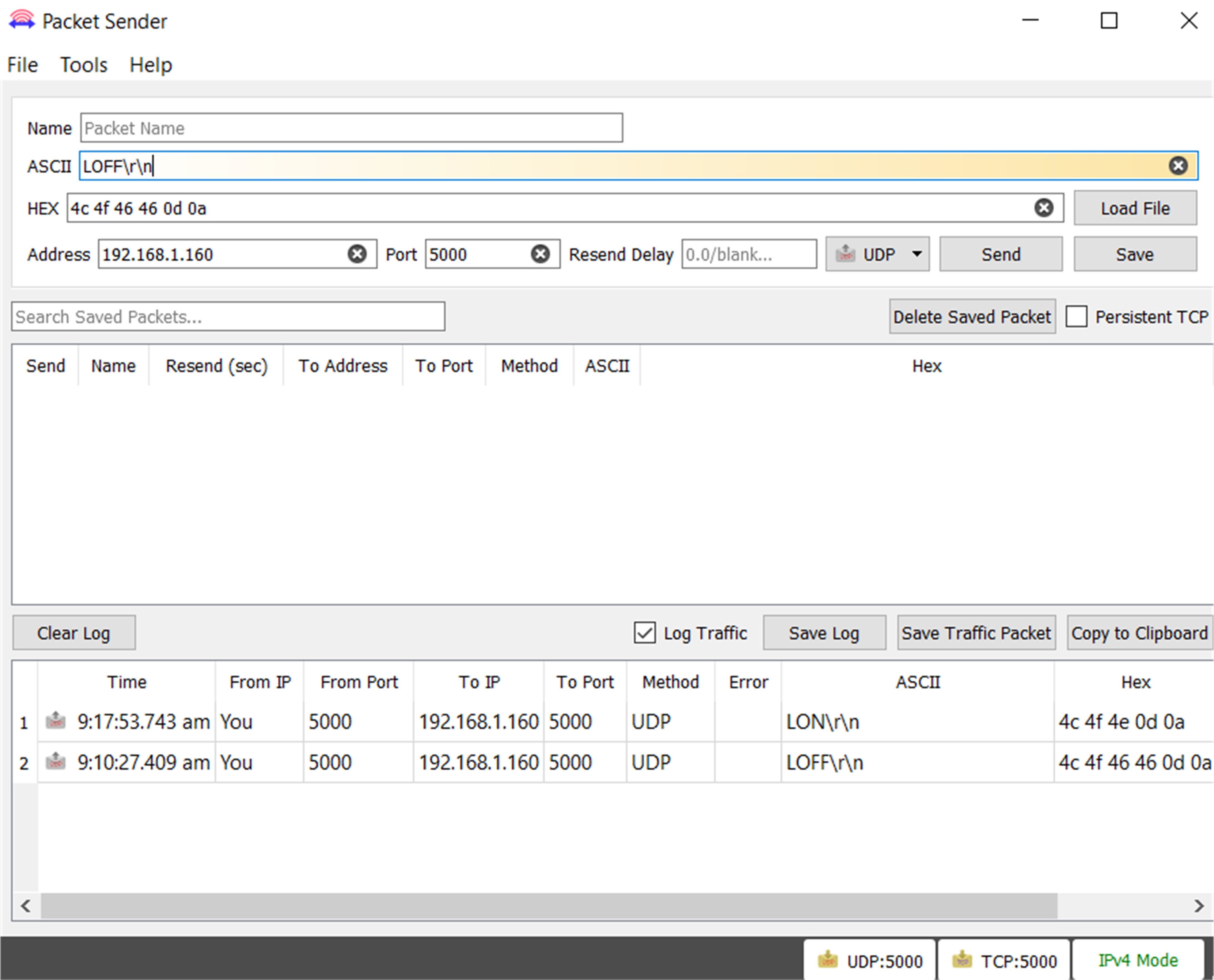
Testing the Program
The program can easily be tested using the PacketSender program (see Figure 5) on the PC or using a smartphone after installing a UDP app.
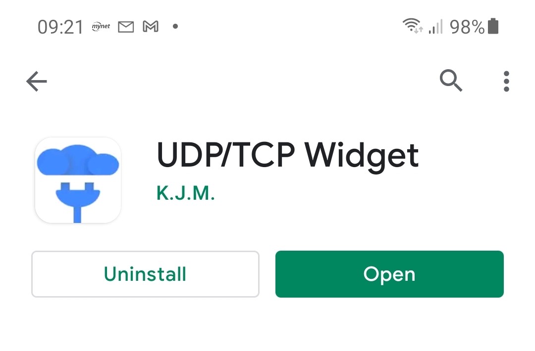
You should install a UDP Server app on your Android mobile phone before starting the test with the smartphone. There are many freely available UDP apps in the Play Store. The one installed and used in this project is called the UDP/TCP Widget by K.J.M, as shown in Figure 6.
The steps to test the program are as follows.
- Construct the circuit.
- Download the program to your Raspberry Pi Pico.
- Start the UDP/TCP Widget app on your mobile phone.
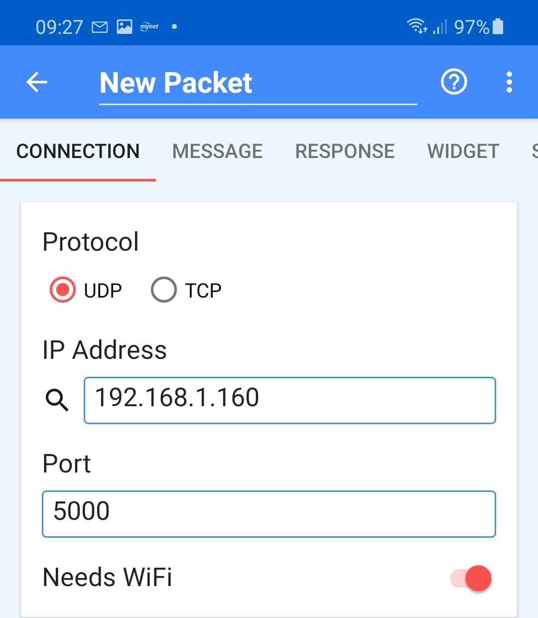
- Click the gear symbol and set the Protocol to UDP, IP address to the IP address of your Raspberry Pi Pico (192.168.1.160 in the author’s Pico), and set the Port to 5000 as shown in Figure 7.
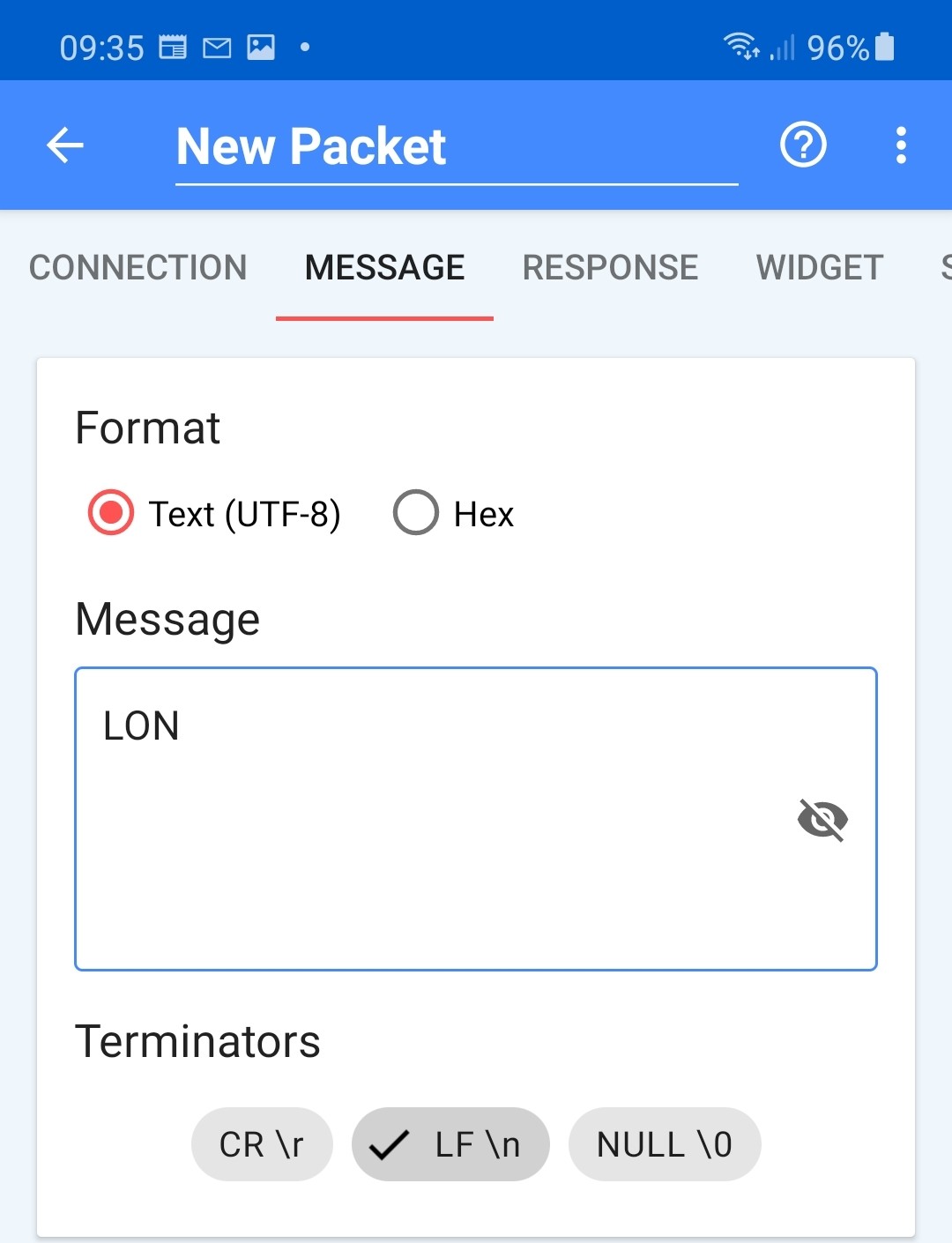
- Click the MESSAGE menu item and select Text (UTF-8) as the Format, and enter command LON to turn ON the LED. Select LF\n as the Terminator and click the OK symbol (check symbol), as shown in Figure 8.
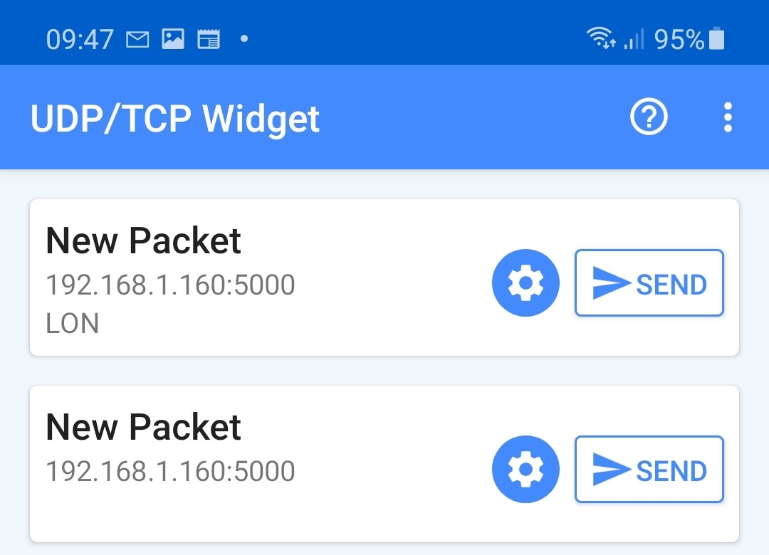
- Now, click the SEND button (Figure 9) to send the command to the Raspberry Pi Pico. You should see the message Packet Sent displayed at the top of your Android screen temporarily.
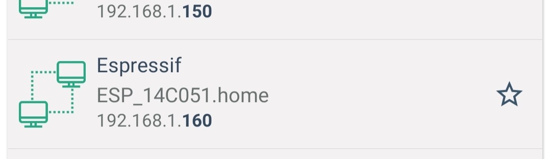
Notice that the IP address of the ESP-01 can be obtained by scanning all the devices on the local Wi-Fi router. For example, the Android app called Who Uses My WiFi – Network Scanner by Phuongpn can be used to see the IP addresses of all the devices connected to your router. The ESP-01 is listed as shown in Figure 10 (IP: 192.168.1.160), with the name Espressif.
Editor’s Note: This article is an excerpt from the book Raspberry Pi Pico Essentials, reformatted and lightly edited to match Elektor Magazine standards and page layout. Being an extract from a larger publication, some terms in this article may refer to discussions elsewhere in the original book publication. The author and editor have done their best to avoid such instances though, and are happy to help with queries. Contact details are in the Questions or Comments? box.
Questions or Comments About the Raspberry Pi Pico?
Do you have any technical questions or comments related to this article? Then email the author at d.ibrahim@btinternet.com or Elektor at editor@elektor.com.
Discussion (0 comments)