
Small Experiment: Skin Impedance and Capacitance
on
Many years ago, I encountered some strange effects involving wires in water and fingers touching metallic surfaces. At the time, I wanted to measure wood moisture content using stainless steel screws in the wood. Unfortunately, the characteristics of the contacts changed quickly, resulting in less current flow. It was even possible to build up a charge on the contacts, and I was able to measure a voltage for several seconds after the supply was disconnected. I decided to call this a ‘wood battery’. Only later did I realise that this involved a double layer of water molecules forming a double-layer capacitor. Now I have clarified this mystery with further measurements.
Measuring Skin Impedance
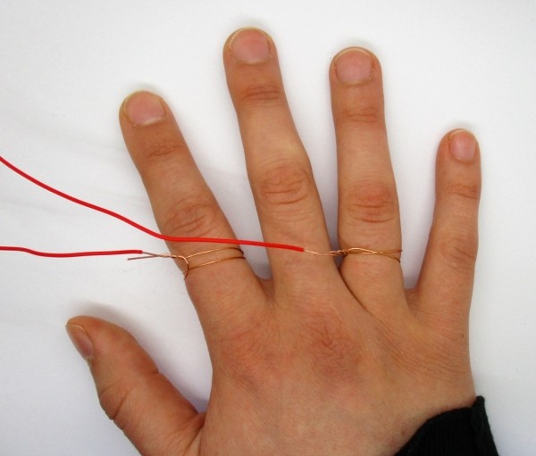
The starting point for the measurements was the development of a conductivity meter for human skin (Figure 1) using a microcontroller, which was ultimately intended to be used as a lie detector. I made the measurements using an AC signal, or, more precisely, a short positive pulse followed by an equally short negative pulse. The result was astonishingly good conductivity values. A normal multimeter shows a resistance of around 1 MΩ between the two contact electrodes, but the microcontroller instrument gives values of around 10 kΩ.
If you do an online search on this topic, you will quickly discover that skin impedance is frequency-dependent. The higher the frequency, the higher the conductivity. The impedance also drops with increasing voltage. Investigations like this are performed for a variety of reasons. At one time it was about the dangers of electricity. Researchers investigated how much current could flow through the human body under various conditions. This revealed that the internal impedance from hand to hand is only a few thousand ohms, and the skin impedance is dominant. With high AC voltages, the contact resistance becomes very small, and the internal impedance is therefore dominant. This means that electric shocks are more dangerous than you might think from an ohmmeter reading.
The other focus of such investigations lies in the medical domain. The aim is to find out how ECG electrodes work or what conclusions can be drawn from the body impedance. These investigations reveal that the contact resistance can change over time during the investigation and that it can be influenced by a saline solution. The impression remains that the skin is a very complex organ.
An Equivalent Circuit for the Skin
What an electronics hobbyist or engineer actually wants is a usable equivalent circuit for small signals. Up to now this has usually been assumed to be a resistance on the order of 100 kΩ to 1 MΩ, but this is apparently only valid for low DC voltages up to approximately 9 V. The behaviour of the skin is different with AC voltages. So, I switched on my sinewave generator and built a voltage divider consisting of two fingers and a fixed 10-kΩ resistor.
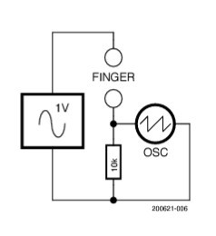
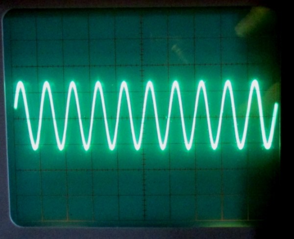
Measurements with low voltages around 1 V (Figure 2) showed that the current waveform was an undistorted sinewave (Figure 3). The strong frequency dependence could also be confirmed. Between 1 kHz and 10 kHz the impedance dropped by around a factor of 10. My hand with the two wire electrodes was thus behaving more or less like a capacitor. Comparisons with different capacitors from the parts bin showed that a 3.3-nF capacitor showed very similar behaviour.
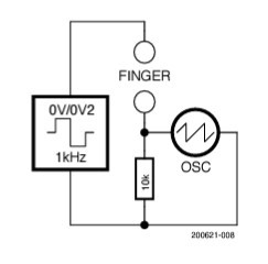
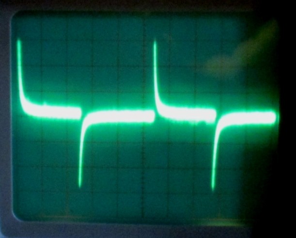
The entire measurement process can be simplified by using a square-wave signal (Figure 4). For this I used the test signal from the oscilloscope, with an amplitude of 0.2 V and a frequency of 1 kHz. This is not an AC voltage, but instead pulsed DC. The output voltage is zero for 0.5 ms and then 0.2 V for 0.5 ms. This signal can be regarded as a DC voltage of 0.1 V with a superimposed squarewave signal having a peak amplitude of 0.1 V.
The result is the typical pulse waveform of an RC high-pass filter (Figure 5). Since the measuring signal has a DC component, it is clear that the DC conductivity is insignificant, as otherwise the output signal would be noticeably offset in the pulse region. This also confirms that skin with two wire electrodes behaves like a capacitor with a capacitance of a few nanofarads. In parallel, there is a high resistance of around 1 MΩ.
An Explanation
The large capacitance of a several nanofarads with the very small contact areas of the wires gave me the idea that what is actually formed here is a double-layer capacitor. The skin moisture produces a water film on the metal surface. A double layer of polarised water molecules is then formed on the boundary surface. This would be exactly the same as the operating principle of a supercapacitor, in which a graphite coating provides an especially large boundary surface.
This sort of capacitor can also be formed with two copper wires in pure water (Figure 6). The measuring circuit is still the same. To obtain comparable results, the wires should only be immersed about 1 mm into the water.
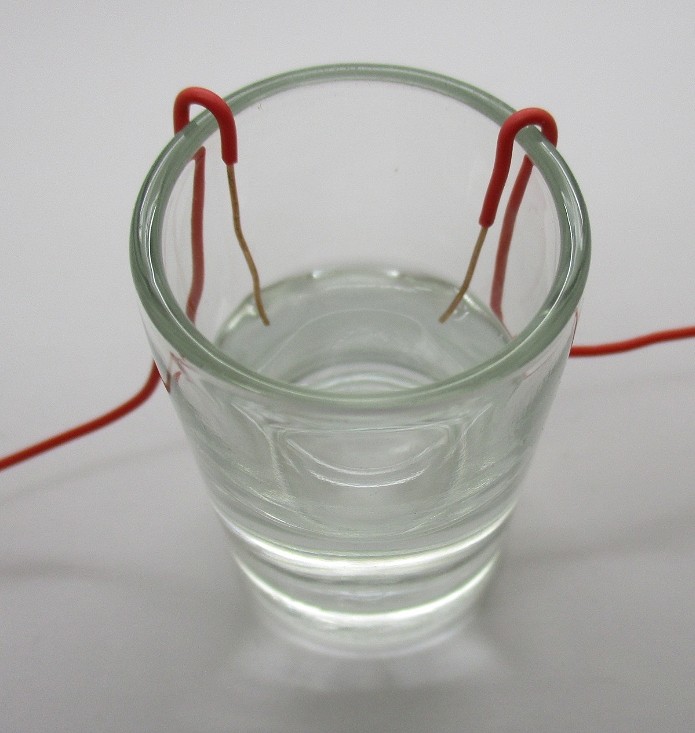
The measurements (Figure 7 and Figure 8) show that the glass of water with two electrodes has more capacitance than my hand. The capacitance can be calculated from the waveform, but it can also be determined by comparison with other capacitors. The water capacitor has approximately the same effect as a 47 nF film capacitor, despite the very small surface area of the electrodes immersed only about 1 mm into the water. If you need more capacitance for some reason, it’s not a problem.


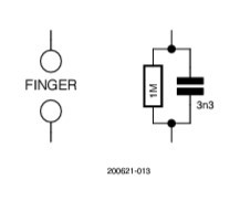
In summary, the result is clear: the impedance of two fingers with wire contacts corresponds to the equivalent circuit in Figure 9. The exact result, however, can vary significantly from one person to the next and is, of course, very strongly dependent on the contact area, the instantaneous skin moisture level and the contact pressure.
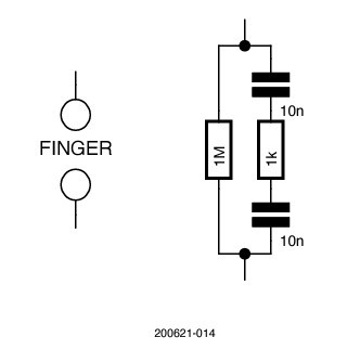
If we examine this capacitor in more detail, it turns out to actually be two capacitors. The dielectric of these capacitors is the thin water layer between the skin and the metal electrode. In addition there is naturally the inner impedance of the body, for example, between one finger and another. All in all, this leads to a more extensive equivalent circuit (Figure 10). The internal impedance is difficult to determine, and for the sake of simplicity, it is here assumed to be 1 kΩ.
If you repeatedly increase the frequency, the impedance of the skin capacitor drops accordingly. Then the internal impedance becomes more significant. I personally know this from painful experiences in amateur radio. If you accidentally touch the output connector of a shortwave transmitter, you don’t get an electric shock but instead a burnt finger. The burn effect, however, is totally different from what you get from touching a hot soldering iron. There is no burn blister like you get from a soldering iron, and it feels completely different. The heating clearly occurs beneath the epidermis in the deeper skin tissue with higher conductivity, in particular where the current density is highest.
Application: Touch Sensor
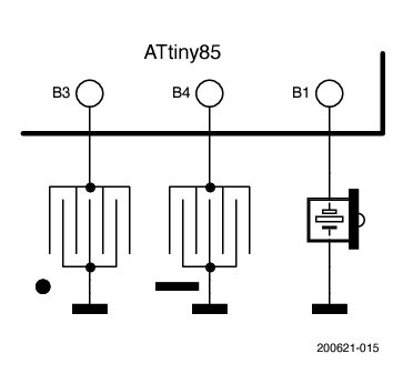
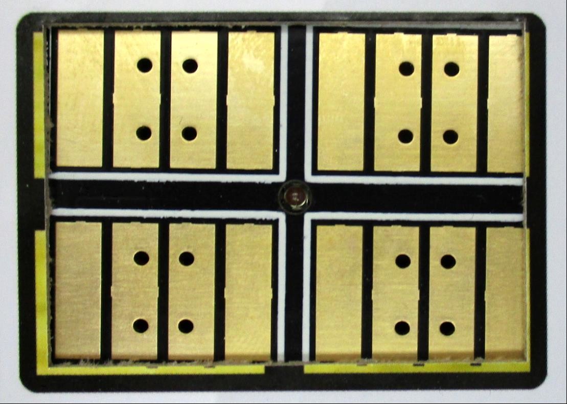
A possible application for the finger capacitor is an automatic Morse key with touch sensors. I used an ATtiny85 microcontroller (Figure 11) together with two touch sensors from an FM radio (Figure 12). In the radio the sensor currents were amplified by transistors, which means that the skin resistance was sensed. This has the disadvantage that a certain degree of soiling can lead to malfunctions.
An evaluation method in which the microcontroller measures the charging time of the capacitor formed by the finger is significantly more reliable (see Listing 1).
Listing 1: The Morse key.
’ELbug with touch sensors
$regfile = "attiny85.dat"
$crystal = 8000000
$hwstack = 8
$swstack = 4
$framesize = 4
dim n as byte
ddrB = &B00011010
Portb = 0
Do
DDRB.3 = 0 ’ B3 high impedance
Portb.3 = 1 ’ pullup
waitus 10
if PINB.3 = 0 then ’ still low after 10 µs?
portb.3 = 0
ddrb.3 = 1
for n = 1 to 50 ’ output dot
PortB.1 = 1
waitms 1
portb.1 = 0
waitms 1
next n
waitms 100
end if
portb.3=0 ’ discharge B3
ddrb.3 = 1
DDRB.4 = 0 ’ B4 high impedance
Portb.4 = 1 ’ pullup
waitus 10
if PINB.4 = 0 then ’ still low after 10 µs?
portb.4 = 0
ddrb.4 = 1
for n = 1 to 150 ’ output dash
PortB.1 = 1
waitms 1
portb.1 = 0
waitms 1
next n
waitms 100
end if
portb.4=0 ’ discharge B4
ddrb.4 = 1
waitus 10
Loop
End
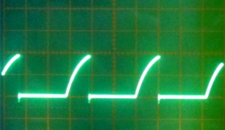
For this a port (B3, B4) is first configured as an output and switched low to discharge the capacitor. Then the port is put into the high-impedance state and the internal pull-up (approximately 50 kΩ) is enabled. The sensor capacitor then starts charging. The critical point is when the port voltage rises above the threshold level of around ½ VCC. For the task at hand, it is sufficient to wait 10 µs and then read the port state. If a low state is detected at that point, the key is regarded as being pressed. In this case a square-wave signal as a feedback tone is generated for the piezo loudspeaker connected to B0. Figure 13 shows the situation with a too-light touch. There the pulses rise to 4 V within 10 µs, so the key is regarded as not pressed.
In the next edition of Elektor (the Summer Circuits 2022 issue), I will show two other application circuits: the finger capacitor and the two-finger organ. Until then, I hope you have a lot of fun with your own experiments!
Questions or Comments?
Do you have technical questions or comments about this article? Email the author at b.kainka@t-online.de or contact Elektor at editor@elektor.com.
Discussion (7 comments)