Do you have a need to find faulty capacitors? High ESR can lead to problems. Back in 2002, Elektor published an article about a DIY in-circuit capacitor tester, and the Elektor Lab team designed the PCB.
Do you have a need to find faulty capacitors? High ESR can lead to problems. Back in 2002, Elektor published an article about a DIY in-circuit capacitor tester, and the Elektor Lab team designed the PCB.
ESR Capacitor Tester Circuit
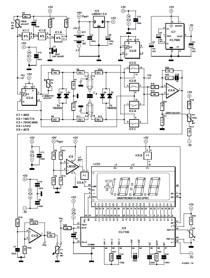
Take a look at the circuit. The author explains: "A 200-kHz square wave generator is built around IC1. This signal is divided in IC2.A which in fact constitutes our bipolar 100-KHz test signal generator. Series resistors R6 and R3-P3 on the Q and *Q outputs of IC2.A give the generator a high output resistance compared to the low ESR, and, essentially, make the generator act as a 100-kHz, balanced, constant current generator."
Circuit diagram of the Capacitor ESR Tester. Cx is the capacitor under test.
"The voltage drop across the C.U.T. is taken to IC3, four bilateral switches coupled as a controlled polarity changer, changing polarity in sympathy with the outputs of IC2.A. This enables IC3 to act as a (rudimentary) ADC. IC4.A, a differential amplifier, converts the differential signal into a single-ended signal, i.e., one which is referenced to ground. IC4.B amplifies the signal such that it can be applied to a 200-mV voltmeter. IC9 is the voltmeter IC, here the ICL7106 is used with an LCD, all in a standard configuration. The LM358 in position IC8 is a comparator that tells you when it’s time to change the battery. IC7, finally, generates the negative supply rail for the circuit."
In-circuit capacitor tester
Subscribe
Tag alert: Subscribe to the tag Test & Measurement and you will receive an e-mail as soon as a new item about it is published on our website!
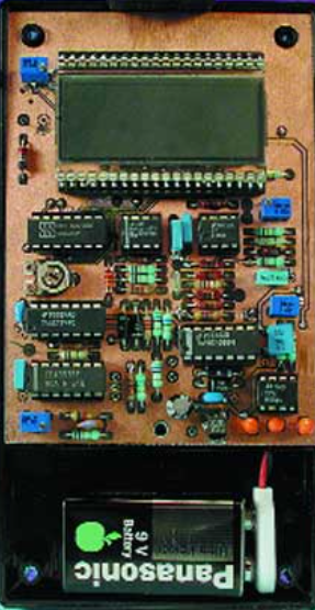
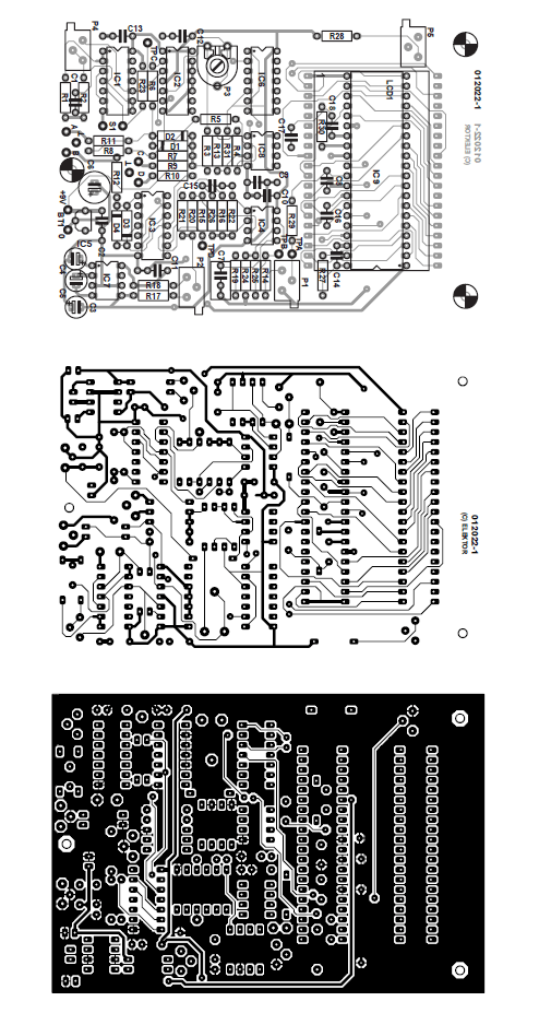
The PCB
Elektor's lab team designed a compact PCB for the Capacitor ESR Tester. The result was a double-sided through-plated board design. The board was designed so that all adjustment points were easily accessible from the sides of the board (multiturn presets P1, P2, P4, P5) and from the top (preset P3).
Copper track layout and component mounting plan of the PCB.
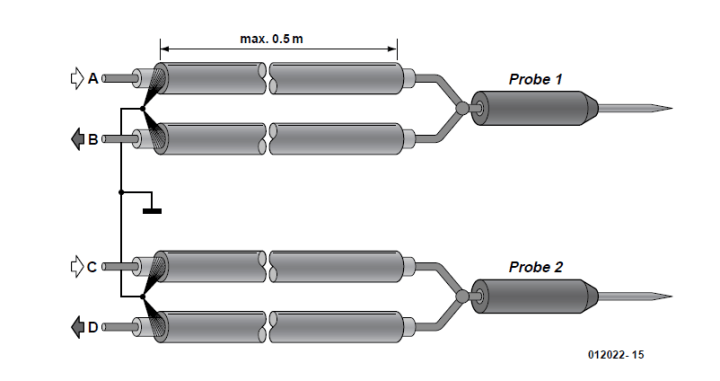
The nearby image shows the probes. The two wires are soldered together as close to the probe tip as possible. In this way, the voltage drop along the signal wire will not add to the measurement. The screening ensures that the test leads do not pick up noise, and that you maintain a stable zero adjustment.
Here’s how to make the four-wire test leads between the probes and the instrument proper.
More About the Capacitor Tester
The 2022 article associated with this capacitor tester project appeared in Elektor September 2002. Elektor Members benefit from the magazine, a discount in the Store, and full access to Elektor’s library, which includes the article and many other editions.
Subscribe
Tag alert: Subscribe to the tag Circuits & Circuit Design and you will receive an e-mail as soon as a new item about it is published on our website!
Read full article
Hide full article
Add a rating to this article
★★★★★
★★★★★
Page 1 / 1
Login
No account yet?Register for free!
Forgot password?
Please enter your email address. Instructions for resetting the password will be emailed to you now.


Discussion (0 comments)