SmartScope: Multi-Platform Measuring Instrument
Functionality (cont.)

has very few control elements, as most
settings are done via the touchscreen or mouse
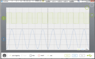
This does take some time to get used to. But once you’ve found out how to change a setting (such as changing the input gain using a pinch/stretch gesture with two fingers) it soon becomes second nature. Each signal has an identically colored circle to the left of the grid, which hides a number of functions. When you touch it or click on it with the mouse a small menu appears that lets you set up the AC/DC coupling, triggering, probe attenuation or hide the signal. There is a similar circle at the right of the grid. The menu associated with this lets you select the trigger channel and either the rising or the falling edge for triggering. A status box can be displayed that shows the settings and a lot of detailed information about the signal. When it is no longer required, you can just drag it off the screen.
At the top of the display you can call up the hardware memory buffer. This shows the full contents of the buffer (4 Msamples). From here you can quickly and easily select a section that interests you so you can look at it more closely.
The menu on the left has a section that lets you set up the AWG. At the moment the user can choose from a number of standard wave forms, or import a user-defined signal from a CSV file, which can be stored in Dropbox or a local hard drive. One thing that stands out is that a number of digital decoders are included as standard with the software. It’s unusual to see this for products in this price range (you would expect to pay for these as an extra). These decoders are used to unravel different types of digital formats and to display things such as the actual values and addresses of the data. At the time of writing, there are decoders for I²C, 3-wire and 4-wire SPI and UART included with the software, and there are more to follow. It is also possible for users to write their own decoder, and to make it available to the SmartScope community. Such a decoder consists of a single DLL file, which should be added to the SmartScope system folder. This has been set up in such a way that it can work across all platforms without modifications. It’s quite possible that some features have not been mentioned, but at least you should now have a good idea what this scope is capable of.
Read full article
Hide full article


Discussion (1 comment)