
Soldering: A Closer Look at Current Soldering Technology
on
Most people don’t realize that soldering electronic components is a very complex activity with complicated thermal and chemical processes taking place in a very small space. However, if you follow some basic rules, you won’t run into trouble.
Solder joints should do more than just make good contact: they also need to be mechanically strong and they shouldn’t oxidize. In addition, they should be free of chemical residues, such as flux, since flux can attack nearby metallic surfaces as well as plastics.
Solders are generally divided into three categories: consumer, industrial, and high-end. The latter is used in areas such as automotive or environments where life or health is at stake. As makers, we are mainly interested in manual soldering for DIY construction and development.
Good Old Lead Solder
Lead solder was standard for many years. It has good wetting and flow characteristics and a relatively low melting point of around 183°C. Following the rule of thumb that the working temperature at the soldering tip is equal to the melting point of the alloy plus 120°C, this corresponds to a soldering temperature of approximately 300°C.
The flux in the solder wire is intended to dissolve oxides at the solder joint. The tin in the solder amalgamates with the copper (or other metallic layer) to produce an intermetallic diffusion zone consisting of an alloy of the two metals. This normally results in a well-formed solder joint, durable and with good mechanical strength.
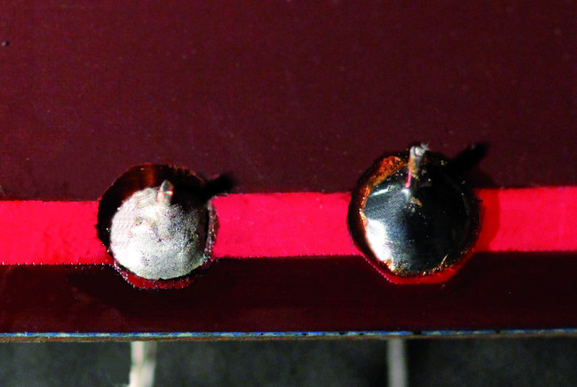
Unfortunately, this is not always the case – sometimes you get a cold solder joint (Figure 1). Cold solder joints are caused by highly oxidized metallic layers, dirt, the wrong temperature, or early solidification during the melting process. Cold solder joints have excessive joint resistance and can even lead to the detachment of components. The electron microscope images in Figure 2 show the deficiencies of a cold solder joint compared to a good solder joint.
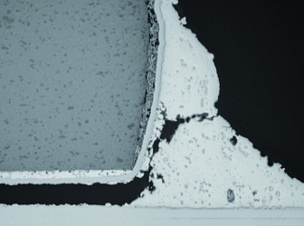

with good contact (source: Infineon).
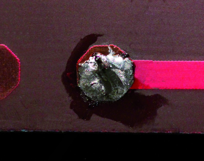
In the days of lead solder, cold solder joints were clearly recognizable due to their dull matte surface, instead of the glossy surface of a good solder joint. Unfortunately, this is no longer true with lead-free solders. With the new alloys, solder joints usually have a matte surface depending on the specific composition, whether they are cold or good (see Figure 3).
Lead-Free in the New Millennium
The introduction of lead-free solder in 2006 has made manual soldering a bit more difficult. The new solders are designated as RoHS-compliant, which means they conform to the EU Directive on the Restriction of Certain Hazardous Substancesi.
Lead-free solders are not allowed to have more than 0.1% lead content. This is mainly intended to prevent the inhalation of toxic vapors, but the risk of this was actually fairly low because suitable extraction systems were available (assuming they were used). For a long time, people were not aware of the hazards of working with lead. For example, in the old days, a professional typesetter would lose all their teeth within a few years due to the lead type.
Soldering Tips are Hotter Now
Anyone who works with lead-free solder for the first time notices right away that the new solder needs a significantly higher temperature and has different flow characteristics. Many components do not like such high temperatures, so efforts have been made to counteract them by means of innovative fluxes and shorter soldering times. All this makes lead-free solder wire more expensive (see below). This also means you should be on guard against especially cheap lead-free solder wire, which often is not what it claims to be. If you work with too high a temperature, you can easily damage a sensitive component or, what’s worse, quickly detach a solder pad from the PCB.
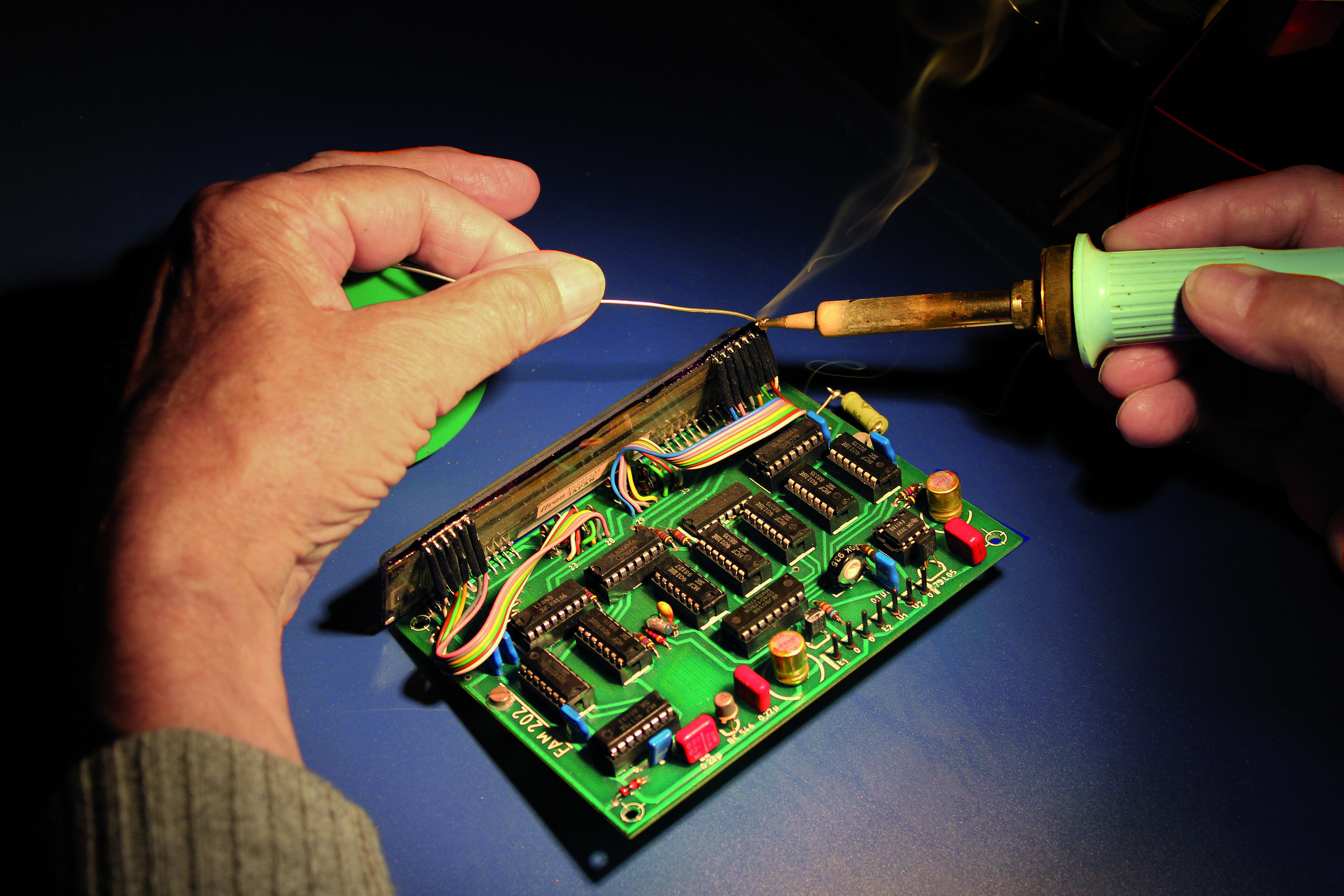
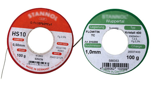
Hobby developers and makers are still allowed to use lead solder, as long as they do not distribute their products on a commercial basis. This means that selling relatively large numbers of things you make in your home lab is not allowed. Figure 4 shows that along with RoHS-compliant solder, ‘makers’ are still using lead solder.
What’s in Solder?
Most of the lead-free alloys commonly used now have a significantly higher tin content. Previously it was approximately 63%, but now it is around 95%, depending on the manufacturer. This raises the melting point of the alloy to the range of 217°C to 227°C. Previously, the tin in the solder was the component that formed the intermetallic zone and was able to amalgamate with the solderable metal surfaces.
Lead was always the inactive component of the alloy, with the advantage that it made the solder wire cheaper and reduced the melting point of the tin from 232°C to 183°C. With more tin in the solder now, along with a higher soldering temperature, you have to pay a bit more attention to your tools and to component metallization. The solder not only amalgamates faster with copper surfaces but also strips copper from the surface faster.
Why Is Lead-Free More Expensive?
With standard lead-free alloys, the previously mentioned melting temperature of 217°C, one of the lowest possible melting temperatures, can only be achieved in the usual composition with an alloy consisting of 95.5% tin, 0.7% copper, and around 3.8% silver. This alloy has the advantage of a relatively low melting point, but the disadvantage is that the silver content of slightly less than 4% can easily make the solder wire twice as expensive.
This silver-containing alloy can basically be made more economical by reducing the silver content to 3%. Then, the alloy will have a melting temperature range of 217–223°C, which is not especially noticeable for soldering or for the life expectancy of the solder joint.
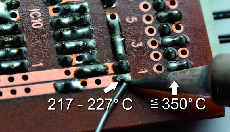
More economical alloys consist, for example, of 99.3% tin and 0.7% copper, resulting in a defined melting point of 227°C. For this, it is not absolutely necessary to raise the temperature of the soldering tip by 10°C compared to an alloy containing silver (Figure 5).
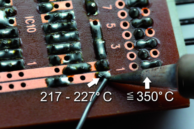
Temperature Limits Should Be Respected
In theory, the soldering iron temperature would have to be set to 350°C for the last-mentioned lead-free solder. If you need 10 to 20°C more to input a certain amount of heat in a short time, that’s certainly possible, but temperatures above 380°C usually damage the board and the components more than they help with soldering. The flux in the solder wire core also burns significantly faster and can only do its job for a certain time at a certain temperature. Each 10°C increase in temperature cuts the active life of the flux in half; the time available to remove the oxides gets shorter, and at some point, it’s not long enough.
The above-mentioned alloys naturally differ from one manufacturer to the next, and they can certainly contain additional components. For patent-related reasons, manufacturers usually do not disclose that information.
Soft soldering always involves inputting the required amount of energy and reaching a certain minimum temperature. The solder must be liquid and have a certain temperature above the melting point. This enables the amalgamation of the metallic layers to form a strong solder joint. All of the previously mentioned lead-free alloys are sufficiently durable. Very roughly speaking, the solders containing silver are better suited to applications with stronger temperature cycling, which is often accompanied by persistent mechanical stress or vibration. This applies, in particular, to the previously mentioned high-tech deployment in automotive electronics or medical equipment.
The Solder Should Flow Well
Solder wire consists not only of an alloy but also of the previously mentioned flux. In the very early days, there was no solder wire with a flux core, so people made do with solder pastes or even homemade flux. A common recipe consisted of trichloroethylene mixed with rosin, which went by the name ‘soldering honey’.
The task of a flux is to remove the oxides from the parts concerned: the component, the circuit board, and, of course, the liquid solder. This should happen for as long as possible, in order to give the longest possible time window for soldering.
A distinction is made between halogenated and non-halogenated flux. Both types remove oxides by means of an acid–metal oxide reaction. With lead-free solders, this reaction must take place at higher temperatures, and it must be active longer at higher soldering temperatures. The flux must be able to flow ahead of the solder in sufficient quantity, remove the oxides, carry the resulting salts away from the solder, and leave the liquid solder with a nice, clean, purely metallic surface. On the other hand, there should not be too much flux present, so that excessive residues do not have to be removed afterwards. Solidified flux is not only unattractive but (contrary to popular opinion) it usually remains chemically active, so you should, in any case, be careful.
Lead-Free Solder Needs a Bit More Energy
More energy is needed for a lead-free solder joint than for a conventional lead solder joint. As the required amount of energy is higher, you should regard heat transfer to the solder joint as an important aspect of soldering. Every soldering task requires a soldering tip with a suitable heat transfer surface so that the higher energy needed to melt the lead-free solder does not have to be achieved solely by raising the working temperature.
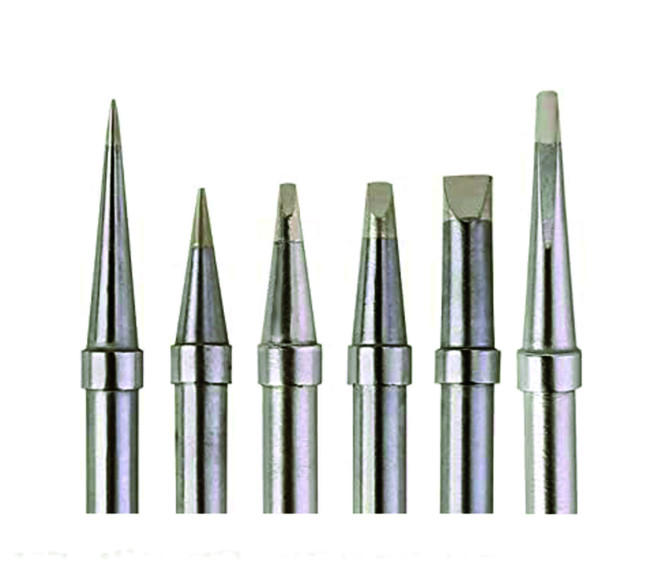
Selecting the right soldering tip (Figure 6) is, therefore, an important consideration, as is continual cleaning of the tip, since it also oxidizes and becomes covered with scale under high heat stress. The contact surface of a soldering tip also tends to get hollowed out after long use. This significantly reduces the effective heat transfer.
Studies have shown that when using lead-free alloys, raising the temperature (for example from 360°C to 410°C) has a nearly exponential effect on soldering tip wear and significantly shortens the lifetime of the soldering tip. For this reason, it is generally advisable to use a slightly longer soldering time or contact time instead of increasing the working temperature. A soldering station rated at 80 W or higher would be the right choice.
Lead-Free Soldering Is Different
Lead-free soldering is not more complicated; it’s just different. First of all, you need to become familiar with the different spreading and wetting characteristics of lead-free solder. You also need a slightly longer soldering time, to avoid raising the soldering temperature unnecessarily. Actually, not that much has changed. It’s advisable to try a number of different solders to find the one you like best. Generally speaking, solders with relatively high silver content are preferable, even if they cost more.
Now we're no longer exposed to lead vapors, but the actual fumes come from the flux, and nobody knows exactly what is in the flux. A solder vapor extraction unit (even a small one) is, therefore, still a good investment.
(210653-01)
Editor's Notes: Soldering Resources
The well-known manufacturers of soldering products offer an amazing amount of general information on the subjects of lead and lead-free solder wire, fluxes, soldering tips, instructions and practical tips, and much more, all for free download.
- Soldering stations in the Elektor Store
- www.felder.de/downloads/allgemeine-informationen.html [German]
- www.stannol.de/en/downloads.html
- www.almit.de/index.php#Goodtoknow
- www.almit.de/soldering-tips-and-working-life
Translation: Kenneth Cox
Discussion (1 comment)