Small brushed DC motors are still widely used, from electric seats in automotive to power tools, so even though brushless motors seem like the future, it is still worth understanding how this technology is integrated into electronic circuits. Here we look at PWMs, H-bridges, and some highly-integrated motor control chips.
Small brushed DC motors are still widely used, from electric seats in automotive to power tools, so even though brushless motors seem like the future, it is still worth understanding how this technology is integrated into electronic circuits. Here we look at PWMs, H-bridges, and some highly-integrated motor control chips.
Speed and Direction Control of Small Brushed DC Motors
It’s easy to think that applications needing electrical motors have long since moved to more efficient, brushless alternatives. But brushed DC motors remain a crucial component in a wide range of applications, from automotive and home appliances to power tools and toys. In 2021, the market for such motors was valued at more than $10 billion, according to Data Bridge, and it is expected to continue growing to over $17 billion (USD) by 2029. Therefore, there’s still value in understanding this traditional electromotive technology well.
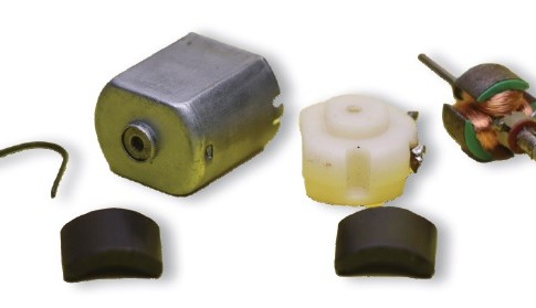
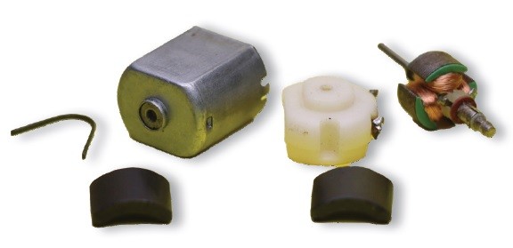
Products at the lower end of the brushed DC motor market are typically termed fractional horsepower (FHP) motors. They consist of a can within which two permanent magnets (PM) are mounted. In the remaining gap fits the rotor with its armature and commutator. An end cap provides support for the rotor and the electrical connection to the commutator via two brushes. The real beauty of such PM motors is the ease with which they are powered. Simply apply a DC voltage and the motor will spring to life with a rotation speed that is linear to the voltage applied.
The component parts of a fractional horsepower DC motor. The commutator is clear to
see on the rotor shaft by the armature coils. (Source: ShutterStock/Pixel Enforcer)
Advantages and Challenges When Using Brushed DC Motors
Applying power and seeing the rotor move displays our first key advantage of brushed DC motors over brushless versions — the simplicity of control. A relay, switch, or MOSFET is all that is required to bring the motor to life. This is a significant difference compared to brushless DC motors that require a significant amount of control circuitry and space to implement the commutation.
Brushed motors are also well understood. After decades of use in various applications, the potential electrical and mechanical failure modes are well understood. Furthermore, the semiconductor industry has developed a considerable range of highly-integrated controller chips targeting these motors, complete with in-built protection and monitoring.
Although they are easy to power and control, brushed DC motors pose various challenges for design engineers. The first of these is lifetime related to the brushes. Over time, the brushes wear away, requiring that they are replaced at some point. Developers typically factor this into their design requirements. For example, electrically adjustable seats and electric doors in vehicles still use brushed motors. Because the motors are only occasionally in use over the vehicle’s lifetime, the brushes will probably outlast all the owners.
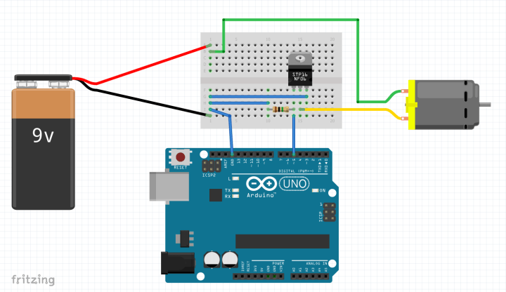
An Arduino together with an appropriately dimension MOSFET can turn a motor on
and off and even control its speed.
Tackling DC Motor Heat Dissipation and Noise
Heat dissipation is another key challenge. Because the heat is generated inside the motor in the windings around the rotor (the armature), the motor casing typically needs ventilation slots and relies on armature rotation to move air across its surface. Heavy loads at low speeds can push the motor to its limits.
In some applications, such as an electrically adjustable desk, the user is recommended to operate the motors for only a few minutes before leaving them to cool. Limiting use is one valid method to tackle such thermal challenges, as long as this limitation does not seriously impede the use of the application.
Finally, noise, both electrical and audible, must be kept under control. Long motor wires can induce currents in nearby cables and printed circuit board (PCB) traces that disrupt the operation of other circuits or cause noise in measurement signals. To minimize the issues, keep wires as short as possible and place small 0.1 µF capacitors across the motor terminals and from the motor terminals to the motor housing.
Ferrite rings on the cables or transient suppressors may also be considered. Motors also vibrate and rattle, so combating audible noise may require sound-absorbing material and careful evaluation of the motor’s mounting. However, this must be balanced with the ability to dissipate heat, so you’ll need to ensure sufficient airflow too.
Speed Control Using Pulse-Width Modulation
Most applications also need to control the speed of the motor. While most of the motor's task may only require simple motion, such as moving a seat forwards and backward or raising and lowering a desk, a premium feel is achieved by slowly accelerating to full speed when starting and gradually reducing speed when coming to a stop. This is implemented using a pulse-width modulated output or PWM.
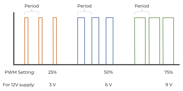
The frequency of such signals is typically fixed, leaving the pulse width to be varied between 0% and 100% of the signal’s period. Using an oscilloscope, the individual pulses are clearly visible. However, when checking with a voltmeter, only the average of the supply voltage is measured (e.g., at 25% with a 12 V supply, 3 V will be measured).
By adjusting the pulse width, the voltage seen at the motor's terminals varies between 0 V and the supply voltage.
There are several things to consider when configuring the PWM. The first is the frequency of operation. Using signals that are audible to humans, such as 1 kHz, can result in an annoying whining sound as the pulse width is ramped up. This is caused by the windings vibrating in the magnetic field and may be exacerbated by a loose rotor mounting that allows motion in cheaper FHP motors. Thus, trying different operating frequencies is worthwhile if such an issue occurs.
The next challenge is starting the motor from a standstill. The armature requires enough electrical energy to overcome the initial torque to start moving. However, once moving, the rotor may be capable of rotating with a pulse width lower than this level. Use of a gearbox or a variable load on the rotor may also change these start and lowest-maintained rotation point pulse width values. This means that, when writing control code, you may need to start the motor with, for example, 10% pulse width, quickly pulling back to, say, 4% once the rotor is in motion to attain minimum speed.
Changing Brushed DC Motor Rotation Direction
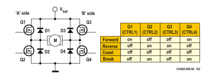
Speed control requires a MOSFET to rapidly apply and remove power from the motor. However, this only allows the motor to rotate in one direction. Support for bi-directional operation requires the use of an H-bridge. As the name suggests, the circuit looks like the letter ‘H,’ with MOSFETs used in the vertical bars and the motor lying in-between in the position of the horizontal bar.
The classic H-bridge circuit, constructed with four MOSFETs, with the motor attached in the bar of the 'H'.
Diagonal pairs of MOSFETs are engaged to turn the motor in one direction or the other. The motor’s speed can also be varied using this circuit by applying a PWM signal to either the lower or upper MOSFET. The choice of upper or lower MOSFETs is irrelevant to the control of the motor. However, if you have other circuitry in the design, such as a resistor and ADC to measure motor current, you may wish to switch the opposite side to minimize noise in your measurements. Ultimately, testing is the best way to determine the optimal solution.
Another capability of the H-bridge is the implementation of an electrical brake. By engaging the pair of bottom-side MOSFETs, the motor’s terminals are shorted together. The back-EMF generated by a still rotating rotor results in a counter torque that rapidly slows the rotor down.
Circuit Protection of H-Bridge Circuit
One potential issue with the H-bridge circuit is that, should a high- and low-side MOSFET be engaged simultaneously, a short circuit will result, leading to catastrophic failure. To avoid this, it makes sense to use one of the many dedicated brushed DC motor drivers available. Such devices stop short-circuits from happening and additionally provide over temperature, open load, and under voltage protection, together with feedback to a microcontroller via a GPIO or SPI interface.
Motor driver ICs like this TC78H660FNG from Toshiba integrate an H-bridge along with protection
mechanisms. (Source: Toshiba Electronics Europe GmbH)
Special devices targeting automotive, known as System Basis Chips (SBC), are also available, integrating CAN and LIN transceivers and low-dropout regulators (LDO) for supplying a microcontroller. One example is the MOTIX range from Infineon, such as the TLE9561QX, that supports up to two brushed DC motors in H-bridge configuration, but requires the designer to select appropriate N-channel MOSFETs to match the motor and application.
System Basis Chips (SBC), such as the MOTIX range from Infineon, also include a CAN
transceiver and a low dropout regulator alongside the brushed DC motor control circuitry.
These particular devices require external MOSFETs. (Source: Infineon AG)
High Integration Makes for Simple Brushed DC Motor Control
Controlling brushed DC motors has never been simpler, with a range of highly integrated chips available from semiconductor vendors. With some even integrating the power MOSFETs, the internal logic ensures that the H-bridge cannot be accidentally placed into a short circuit. Further features, such as over temperature, over-current, and open circuit detection, provide developers with plenty of feedback on the status of both the H-bridge and the motor that can be used to provide diagnostic output to users. Investing time to understand this well-established technology still makes sense, despite the rapid uptake of brushless technology, as brushed DC motors will continue to find a home in home appliances, toys, and automotive for years to come.
Elektor Magazine has been one of the leading sources of information on electronics for engineers, designers, start-ups and companies for 65 years. Our magazine is powered by an active community of electronics engineers – from students to professionals – who are passionate about designing and sharing innovative ideas.
For them, we publish hundreds of items a year, in formats such as articles, videos, webinars, and other learning formats. Our mission is to share knowledge in every possible way and inspire readers with the latest developments within the electrical engineering sector.
Thank you for your vote!
Leave further comments in the fields below.
Thank you for your vote!
If you wish to leave a comment with your rating, please first use the login below. If not, just close this window.


Discussion (0 comments)