[Partner Content] The time required for software development of a drive control system can be reduced using models for testing. With the model-based approach software tests can be done in a simplified test environment.
The time required for software development of a drive control system can be reduced using models for testing. With the model-based approach software tests can be done in a simplified test environment. The usual hardware test setup including the physical motor and power electronics can be omitted. A small, HIL system that fits on your desk is sufficient.
The triumph of electric motors has been one of the most important companions of the industrial revolu-tion since their invention in the 19th century, and the success story continues. Electric drives are every-where. From powerful generators in power production to millimeter-sized micro drives and smaller. The basic electromagnetic principle has not changed since then. In addition, numerous basic operating prin-ciples have evolved. The most important variants are the DC motor, asynchronous motor, synchronous motor and the brushless DC (BLDC) motor, which is actually a three-phase synchronous machine. Each operating principle has specific characteristics that are suitable for corresponding tasks. For example, the DC motor is considered a robust and cost-effective all-rounder, only its commutator for turning the cur-rent to achieve continuous rotation subject to wear. The brushless DC motor - also known as an elec-tronically commutating DC motor - on the other hand, contains hardly any wear parts, has a long service life and is therefore very well suited for continuous operation with high power density.
Adapting motors to their intended use
To fulfill the function of the application, there are many parameters that must be controlled, and moni-tored. Depending on the motor design, parameters such as current, voltage, magnetic field strength, position of the rotor, etc. must be adapted to the work profile for operation. In addition, there are envi-ronmental conditions that influence the operation of the motor. The environmental conditions, repre-sented by variables such as temperature, pressure, humidity, vibrations, requirements for operational safety and much more, influence the design of the motors and their control system.
Programmable, powerful, and cost-effective microcontrollers - 8, 16 or 32 bit - have now become main-stream for these tasks. They process control signals sufficiently fast for motor control. SSoftware can be used to adapt the control to the environmental variables, and they process the data from the in-put/output interfaces for operation. Programs, e.g., for a microcontroller-controlled drilling machine, now easily reach half a million lines of program code and more.
Challenges in the development process
Software for drive controls is usually extensive and complex. Larger teams usually work on components such as control algorithms, safety systems, drivers, and hardware-related software as well as on the application programs. Due to the parallel development of software and project specific electronics, usually only evaluation boards from the semiconductor manufacturers are available during early soft-ware development phases.
Often, product variants and families must be considered in addition to the basic design of the hardware and software of a controller. This is reflected in additional complexity.
State of the art and project experience
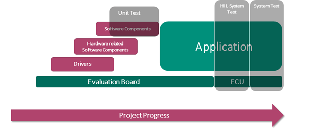
A project usually starts with an eval board for the microcontroller of choice. It is used to develop drivers and hardware-related software. This also includes the software for the motor control. In more complex projects, the programs for communication are also developed here, e.g.: CAN bus protocol, or the power management of the devices (Fig. 1).
Fig 1: The traditional project flow of an embedded system development consists of several stages, which are mainly processed one after the other and only partly in parallel.
The control software parts, that are independent of the hardware, are developed on top of these lower-level implementations. Afterwards the entire application for the device, system, etc. is tackled. The target hardware of the control system - microcontroller control with power electronics (ECU - Electronic Con-trol Unit) - is then usually also available in a first version. This is the point at which traditional hardware-in-the-loop (HIL) test benches are usually used (see Fig. 1). Traditional HIL test setups are usually complex test benches that must be set up for each specific project. They are an expensive and rare resource within the project, which is usually not available to every developer at any time to check newly generated code. Just think of a test environment for a high speed train drive and teams that ideally want to test drivers and hardware-related software of the motor intensively right at the start of the project.
This is one of the main reasons why there is usually little or no testing in the early phases of embedded system development. Individual software components are checked with so-called unit tests, which makes sense and is also well supported by corresponding tools. As soon as the software is to be "married" to the hardware of the end device, however, it becomes problematic.
Why is that?
The target electronics are usually not yet available during the initial software development phases. Development takes place on evaluation boards, for which there are usually no test systems available.
The usual hardware-in-the-loop test systems (HIL systems) are often too large and too expensive to allow continuous testing during development.
Tests with HIL systems and the subsequent system tests usually take place late in the development process. Errors that are discovered late are usually costly to analyze and fix. Test cycles in these project phases sometimes drag on for weeks.
Traditional HIL tests in combination with simulation elements are technically complex and difficult to automate.
Unit tests are poorly suited for testing hardware-related, concurrent, or asynchronous functions, that are part of drivers and motor control software.
For these reasons, many embedded systems are not adequately or even systematically tested in early project phases. The traditional development process therefore has a gap in the testing process - although the experience of developers and companies is that:
a) testing too late leads to project delays and
b) development costs increase exponentially when bugs are fixed late.
How to deal with these realities?
To master the development of complex embedded software, the following methods have emerged as successful:
Introduction of model-based software development methods.
Simulation of functional units that do not yet exist in reality and are only developed step by step.
Very early testing of software components in the development process by introducing integration tests with suitable tools.
Automated testing after every code change (regression testing) through Continuous Integration (CI).
In a model-based development approach for engine control systems, components that do not yet exist in real life are mapped in a mathematical-physical model. Simulink is often used for this purpose. This model behaves like a real motor with its control electronics. The resulting controller software can now be tested against the model and iteratively improved. With this model-based approach, the basic functions can be tested by simulating a real motor-electronics combination, variants can be tried out and the development process is accelerated by the parallelism of hardware and software development.
At a higher level of development, simulations of environmental conditions are important and desirable. If, for example, the load behavior of an electric drive for a train is to be tested in different climatic zones, one can of course place the complete engine with electronics in a climate-controlled chamber and carry out intense tests lasting weeks. However, this is neither timely nor profitable in the early development phase. Early simulations with model-based testing are suitable tools to improve the development efficiency considerably.
The alternative - the introduction of integration testing
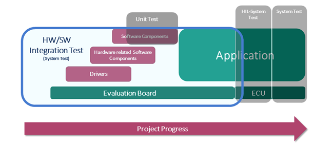
Integration (Fig.2) tests make it possible to detect software errors at an early stage and to correct them quickly. They make it possible to shorten the development time drastically.
Fig.2: Embedded development with integration test
By this test method the real "physics of the application", including many components of the environment of the entire device, and parts of the application are simulated. A suitable hardware platform with software tools is an important prerequisite for this, especially to be able to examine the systems behavior in real time. In a model-based software development environment (tool chain), test cases are generated for the resulting software components. The tests are run against the simulation of the environment. The test hardware is the link between the real-time environment simulation and the software to be tested on the project-specific hardware with an eval board. A separate processor is integrated for the simulation, test execution and error recording. This processor is connected to the eval board of the microcontroller via a wire patch field, which is used to connect the relevant input/output signals.
This entire arrangement has been integrated by Protos into in a complete test system: the miniHIL system. It is specially designed to test software of microcontroller based embedded systems. With the mini-HIL, integration testing, as shown in the blue-framed box in Figure 2, is possible. The test system allows code verification early in the development phase. The real hardware, still to be developed is not required yet. It can even be used to perform parts of the HIL tests early on and to realize and perform large parts of the acceptance tests. Capabilities that have proven to be very helpful and supportive in the develop-ment of safety-critical applications.
Compact HIL system for the developer's desktop
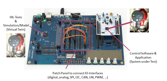
The hardware of the miniHIL (Fig. 3) is not larger than a DIN A4 sheet and easy to set up at the developer's desk. On the right-hand side of Figure 3 is the eval board with the microcontroller, in this case for an STM32. In this example it will later control a circulating pump and execute the entire application for operation.
Control and application together form the System under Test (SUT). On the left side of the miniHIL board, a powerful computer is integrated. It is microcontroller based and if required for higher real-time requirements supported by a FPGA. From a PC, the software development system, the simulation, and test programs are loaded and executed on this part of the miniHIL system. The I/O signals of the device under test (SUT) are connected via wire cables on the patch panel in the center. The functions of the SUT can thus be tested in real time against the simulation running on the left hand side of the board.
Fig.3: miniHIL setup for the development of a pump control system
The advantages of the compact HIL system:
Hardware interfaces are only simulated at signal level and are therefore very well suited for test automation.
Test hardware is largely replaced by software simulation.
Failure behavior can be easily simulated and tested by "failure injection".
The required hardware is much simpler, smaller, and cheaper than conventional HIL systems.
A dedicated test setup for test automation is inexpensive to build and can be kept available for any project at any time.
In HIL tests with power electronics and actuators, the testing of fault conditions, e.g. overcur-rents, short circuits, is sometimes associated with the destruction of components or is danger-ous. In simulation, this is usually unproblematic. With miniHIL, tests are even possible at the desk and not only in the laboratory under special safety conditions.
Software environment and development tools
The tests and environment simulation for miniHIL are developed model driven. The basis for the model-ing is the open-source tool eTrice of the Eclipse Foundation. It includes function blocks for simulation, stimulation and monitoring as well as the handling of automated test cases. The tool enables behavior description via state machines, code generation, integration of typical protocol stacks (in C-code), event-oriented or state-based simulation or testing, and the integration of Matlab/Simulink models via the integration of previously generated C-code.
The test language CaGe (Case Generator) is used to model, generate and execute the test cases - test steps, test sequences and combinatorial tests - for miniHIL. They can be visualized as sequence diagrams. This makes the workflow easy to follow and better to document.
Once a series of tests has been developed on the PC, it is compiled, transferred to the flash memory of the miniHIL computer and executed in real time. By that, the application is tested on the DUT, analyzed and test reports are generated.
This enables miniHIL to rapidly develop and execute integration tests with high test coverage in test cycles of 5 min - 60 min duration, which can take days to weeks with traditional HIL equipment.
Save time and improve code through automated testing
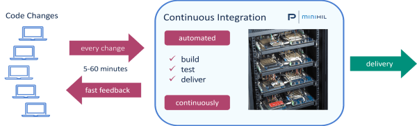
Large and complex software is usually developed in teams whose members work locally and often from different locations. Coordinating code changes in the integration process of individual components on demand is no longer appropriate. To ensure the integrity of the individual program components in any development phase, an automation method from agile software development, continuous integration (CI), is used. In this process, every code change in the project is automatically recorded, built and tested. It is tested early and often so that errors can be discovered and corrected in time.
In addition, regression testing checks not only the new code components, but also the existing ones each time. This means that possible errors caused by side effects are also tested and the overall quality of the software is improved - and it happens quickly. Code can be automated tested every minute for every change. The corresponding reporting makes the tests traceable for the developers and documents the results. This is also the ideal basis for implementing projects more easily and reliably that are required to satisfy functional safety norms.
Fig.4: Continuous Integration process with miniHIL
Figure 4 shows the CI process with miniHIL as described. In the server cabinet in the right picture, several HIL projects can be seen. This is used to test different device configurations simultaneously in an auto-mated manner. With the appropriate IT and server infrastructure, even large teams, local or decentralized, work together efficiently in this environment.
For medical devices, for example a microcontroller control of liquid pumps, this procedure can also be used to "freeze" an already approved device configuration. If necessary, it can then be tested later, easily.
Conclusion
Implementing the software for a complex microprocessor-based drive control system with an end-to-end, model-based process accelerates development and improves the overall code quality. With miniHIL, every change can be tested automatically within minutes. Only through complete and fast test automation can complex software be developed effectively in a team. In one test rack, numerous projects - different hardware and software variants - can be tested in parallel, locally and remotely. Continuous Integration tracks and tests all program changes and ensures code integrity in complex projects. Authors:
Christian Hilden, Head of Development
Peter Schuller, Sales & Business Development
PROTOS Software GmbH www.protos.de
info@protos.de


Discussion (0 comments)