
Tube to Transistor: A Look Back at 1960s-Era Tech
on
At the ripe age of 11, I had my first remembered experience of entering a new decade in 1960. I was in the fifth grade, and was exposed to regular predictions of great advances in science in the 1960s, through articles in Weekly Reader, the elementary-school newspaper our schools provided for us. Having fallen in love with electrical and electronic communication through a science assignment to build a working telegraph, and seeing the walkie-talkie used by Captain Midnight on Saturday morning TV, I was aware of the confidence with which the replacement of vacuum-tube technology by transistor circuits was foretold.
Tube Technology in the ′60s
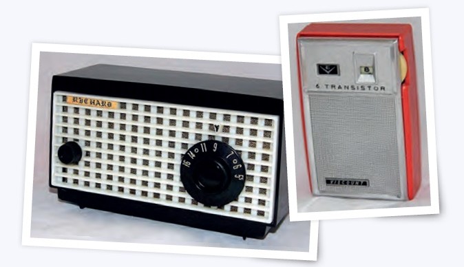
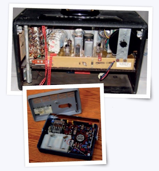
In 1960, most hi-fi listeners had transitioned from mono to stereo, and the rest of the public was at least considering doing so. I was getting used to the “thinner” sound of the new Bakelite-cased GE 5-tube table radio that has replaced our old Arvin, and after going to bed at night, I listened to AM rock stations from several states distant on my new 6-transistor vest-pocket radio. My education about hi-fi had begun via the Allied Radio Electronics catalog.
I was becoming familiar with electronic circuits and stereo equipment performance ratings through Popular Electronics magazine. Amplifier power for stereo systems was rated as the sum of the left and right channels, so a 20 W amplifier was what would now be called a 10-watt-per-channel amplifier. The power rating method varied from one manufacturer to another: some rated in “peak power”, which was about twice the average power; some rated in “music power” which supposedly took into account the maximum listening level with distortion within tolerable limits, and a few rated in “RMS power”, which is a misnomer, and should be called “average power”, being the product of RMS voltage and RMS current that the amp could put out. Most of the tubes were old standbys introduced in the 1940s, such as the 12AX7 dual triode that debuted in 1947, but some of the output tubes were newer. Low-power amps might use a push-pull pair of 7408s per channel. These were essentially 6V6GTs rated in design-maximum terms, giving an apparent increase in plate voltage and current capability. Higher-power amps typically used 6L6GCs, which were introduced in the late 1950s. Continuous average power for a push-pull amplifier was thus about 50 W per channel.
By far the largest market for tubes in the early 1960s was television sets, and most new tube models released during that decade were designed for TV use. A new tube family, Compactrons, was introduced by GE in 1961. These were built on a 12-pin duodecar base, and combined multiple functions in the same envelope. They have been described as being to vacuum tubes what integrated circuits are to transistors. Two beam power Compactrons — the 6JN6 and 17JN6—have been used as audio power amplifiers, with a push-pull pair producing about 20 W per channel. Another new power tube, the 7868 power pentode, was introduced in the 1960s. Often incorrectly called a Compactron, this tube uses a T9 envelope, and thus appears to be similar in size to Compactrons, but not identical in size. It uses a 9-pin Novar base rather than the duodecar base. The 7027 beam power pentode was introduced in the 1960s as well. It is similar to the 6L6GC in performance, but has a different pinout.
Transistor Technology in the ′60s
Although the point-contact transistor was invented in 1947, and the junction transistor in 1948, it was the 1960s rather than the 1950s that proved to be the “decade of the transistor”. The primary reason for this was the need for progress in materials science that would permit transistors to be produced in a way that was cost-competitive with vacuum tubes.
Junction transistors are made of either of two types of semiconductor material. A pure semiconductor—be it germanium, silicon, selenium, gallium, gallium arsenide, gallium arsenide phosphide, or whatever — conducts electricity poorly. This is not because semiconductors intrinsically have high resistance, but because they have a limited availability of charge carriers. When a vacuum tube is powered up, electrons (negative charge carriers) are released from the heated cathode and are attracted to the positively-biased plate. Only under extreme conditions is the plate current limited by the number of available electrons. The semiconductor material used in transistors has impurities added, and these provide additional charge carriers: electrons from N-type impurities, and “holes” (vacancies in electron orbits) from P-type impurities. A transistor consists of two PN diodes constructed back-to-back. Thus there are PNP and NPN transistors.
Initially, most of us understood solid-state devices by analogy with vacuum tubes: the emitter corresponded to the cathode; the base, to the grid, and the collector, to the plate. However, there are two critical differences between transistor and tube operation:
- With the proper voltage applied to the cathode and plate, a tube conducts well, resulting in a large plate current. The tube is “normally on.” However, a transistor is “normally off”: the emitter-base diode must be forward-biased in order for the transistor to conduct. A small leakage current exists in a transistor even with no grid bias; this is called the cutoff current, ICB0.
- Since transistors come in both PNP and NPN versions, the supply voltage (B+ in tube terminology) can be either positive with respect to ground (for an NPN transistor) or negative with respect to ground (for a PNP transistor). So a typical NPN transistor may have emitter, base, and collector voltages of 0 V, 0.6 V, and 12 V, respectively. The base and collector voltages would be negative in a PNP transistor circuit.
The basic amplifier circuits of transistors were also designed by analogy with vacuum tube circuits. The common-emitter, common-base, and common-collector (emitter-follower) transistor circuits could be understood by comparison with common-cathode, common-base, and common-plate (cathode-follower) tube circuits. Initially, common-emitter stages were used as power output stages — both single-ended and push-pull. Although a common-emitter stage could drive a lower-impedance load than a common-cathode tube stage, output transformers were still required by these transistor power amplifiers. In 1953, Sziklai proposed the complementary-symmetry power amplifier, which used an NPN transistor as the upper active device in a “totem-pole” pair, and a PNP transistor as the lower device. Both transistors were connected as emitter-followers, having high current gain, but a voltage gain about unity. These output stages could drive 8Ω or even lower-impedance loudspeakers directly; the necessary voltage gain could be supplied by preceding stages. We DIY-ers were excited by the promise of transformerless power amplifiers. However, complementary NPN and PNP transistors having the necessary matched characteristics were not available at that time, so the circuit was of theoretical interest only. In 1963, Donald Charles Scouten introduced a quasi-complementary symmetry power amplifier design. It employed an NPN Darlington pair and a Sziklai pair instead of an NPN and a PNP output transistor as used in the true complementary-symmetry circuit. The input transistor of the Darlington pair was an NPN unit, while the input transistor of the Sziklai pair was PNP. This arrangement was used because parameter-matched complementary NPN and PNP transistors were not available in those days. The problem is that the Darlington pair’s output transistor was connected as an emitter-follower, while that of the Sziklai pair was connected as a common-emitter stage. The impedances and gains of those two connections do not match, making the quasi-complementary-symmetry output inherently nonlinear, despite the use of heavy negative feedback.
Although by far most transistors are now made of silicon, in the early days, germanium was much less expensive, and hence more common. Although it was known that silicon had five advantages over germanium, it took some years to develop refining and manufacturing techniques to manufacture silicon transistors. The advantages of silicon transistors included:
- Lower leakage current ICB0.
- Lower temperature sensitivity of the collector current; hence, greater thermal stability.
- Greater tolerance of high temperatures.
- Higher Peak Inverse Voltages (PIV).
- Less expensive raw material.
However, the bias voltage required to forward-bias the emitter/base junction is 0.6-0.7 V for a silicon PN junction, compared to 0.2-0.3 V for a typical germanium PN junction. On the whole, silicon was considered superior, and by the mid-1960s, silicon transistors had largely replaced germanium ones in most applications.
Early transistorized push-pull power amplifiers were widely criticized by critical listeners because no stable biasing method that would compensate for transistors’ heat sensitivity had yet been developed. As a result, crossover distortion — a form of distortion that is particularly annoying at low listening levels — was common in solid-state power amplifiers. True complementary-symmetry output stages became common in the 1970s, and temperature-stable, low-crossover-distortion bias arrangements had been developed.
However, the distortion problems of solid-state amplifiers were not over. Finnish researcher Matti Otala published a paper in the IEEE Transactions on Audio and Electroacoustics in 1970, describing transient intermodulation distortion (TIM) in audio amplifiers. Although not specifically limited to solid-state amplifiers, in practice the characteristics of vacuum tube amplifiers rendered them generally less susceptible to this form of distortion. Within a few years of the paper’s publication, most amplifier designers knew how to avoid TIM, and solid-state amplifiers could finally compete — at least in terms of measurements — with tube amplifiers in the contest for good sound.
IC Development in the ′60s
Integrated circuits began as “micromodules” built on ceramic substrates. Jack Kilby of Texas Instruments demonstrated the first working module of a hybrid integrated circuit in 1958. In 1959, Robert Noyce, also of TI, invented the monolithic IC, fabricated from silicon. These early integrated circuits contained only a few transistors: as of 1964, Small-Scale Integration (SSI) devices incorporated 10 or fewer active devices. Medium-Scale Integration (MSI) ICs, each containing 10-500 transistors, became available in 1968.
Radio: AM and FM
Although FM radio was invented in 1933, in 1960 I only knew one family who had an FM set. Many broadcasters owned both AM and FM licenses, and most “simulcast” their programs on both AM and FM, giving listeners little incentive to buy additional receivers, except for the lower atmospheric noise heard on FM broadcasts. The establishment of FM stereo in the U. S. in 1961 added impetus to the FM market, and by 1970, FM stereo receivers were popular; I even had one in my new car!

Home Table Radios
In 1960, the “All-American Five” (AA5) superheterodyne AM receiver circuit was king of the hill in small home table radios. Using a converter (combined oscillator and mixer), IF amplifier, detector/preamp, power amplifier, and half-wave rectifier, these radios used a series-string heater connection for the tubes and a hot-chassis B+, thereby eliminating the power transformer and lowering production cost. Other designs were available using four tubes (either substituting a selenium rectifier for the vacuum rectifier or eliminating the IF amplifier), six tubes (either adding an RF amplifier or incorporating a push-pull output stage), or eight tubes (some combination of RF amplifier, push-pull output stage, and/or dual IF stages). However, being more costly, these latter designs were sold in far fewer numbers than the AA5.

My vest-pocket radio was the only transistor radio I owned during the ’60s, other than car radios. One reason for the slow move to transistor technology in home radio receivers was the limited frequency response of early transistors; though well-suited for audio applications, they did not excel as RF devices.
In the late 1960s, hi-fi manufacturer Fisher introduced the Model 100 FM table radio, a solid-state unit including separate bass and treble controls and a high-quality speaker, as well as provision for connecting an external speaker that was sold separately.
Automobile Radios
The comments above concerning table radios largely apply to 1960’s automobile radios. However, the factors of size and weight, plus the need for a vibrator-type power supply for a tube radio, added urgency for auto manufacturers to offer solid-state models. In fact, Chrysler and Philco introduced an all-transistor car radio as a $150.00 option for the premium Chrysler and Imperial cars in 1955.
In the early 1960s, a number of manufacturers began to offer transistorized radios, but most of these were hybrid devices, using tubes — sometimes “space-charge” tubes designed to run with a 12 V B+ supply, eliminating the need for a vibrator and power transformer. In the earliest hybrid models, the tubes were used as RF amplifiers and/or converters, since they performed better at radio frequencies than transistors did. Some sets used single-ended germanium power transistors connected in the common-emitter configuration, with a power transformer to feed the typically 8-16 Ω speaker. The 1963 Becker Monte Carlo was the first all-transistor auto radio.
Small Portable Radios
Portable radios have been manufactured since Edwin Armstrong’s 1923 model. There was even a one-tube “pocket radio” 12″ long and weighing 4 pounds introduced around 1925. This smallest vacuum tube portable radio was still too large to capture public interest. In 1960, transistorized “vest-pocket” portable radios had been available since their introduction by Regency and Texas Instruments in 1954, but as mentioned earlier, they were very expensive. Prices of vest-pocket radios dropped during the early 1960s, and additional models were introduced, including some larger ones whose fidelity was less limited than that of the vest-pocket models, due to the use of speakers up to 4″ in diameter.
Another portable music player, the Playtape, was a two-track audiotape player system designed by Frank Stanton in 1966 and marketed as a portable music player and a dictation machine. Its 24-minute proprietary tape cartridges typically played two or four songs on a continuous loop. The Playtape was successful among youth, and I read about it in Popular Electronics. However, it was commercially eclipsed by the 8-track player.
FM Converters, Hi-Fi Tuners, and Hi-Fi Tuner-Amplifiers (Receivers)
Audiophiles (AKA “Hi-Fi nuts”) were among the first to adopt FM radio, due to its superior fidelity and greater freedom from noise than AM. One technique used by some audiophiles to receive FM broadcasts was to employ an FM converter — essentially an FM tuner that frequency-shifted the signal to the VHF TV band.
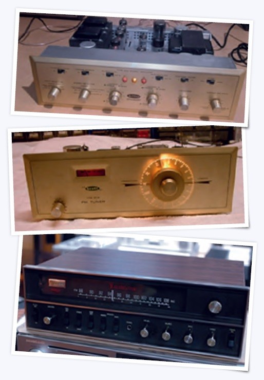
Combination tube-type hi-fi tuners and integrated amplifiers (now known as receivers) were available in 1960, and I read numerous magazine articles discussing whether a newbie should choose a separate preamp, amplifier, and tuner; or a receiver. The main consideration was not one of quality, but of flexibility in case an upgrade was desired in the future. Naturally, only tube-type receivers were available at the beginning of the decade, but by 1969, virtually all new receivers were solid-state, and at least one — The Altec-Lansing 711B — incorporated ICs in the IF strip.
Television
Sony debuted the first non-projection fully transistorized TV in 1960. During the 60s, most of the active devices in TV sets moved to solid-state devices, so that by the end of the decade, only the CRT, high-voltage rectifier, and high-voltage regulator were still vacuum tubes.
By the time I entered High School in 1962, I had developed a somewhat critical ear, and had noticed that TV audio had become a wasteland, with low-power single-ended audio power amplifiers and ultra-cheap speakers. TV broadcasters paid little attention to audio quality, offering limited frequency response and clipping the audio instead of using true compressors to avoid overmodulation. When a member of the audio press questioned a TV executive about poor audio quality, the standard answer was, “the TV sets’ audio is wretched, so why should we do any better?” When TV manufacturers were asked about the poor audio, they usually replied, “the networks give us lousy audio signals, so what’s the point in improving the audio in the sets?"
When ICs first appeared in TV sets, the first application was in the audio systems. Sadly, this change was made for reasons of cost and marketing, and did not improve the audio quality.
Phonographs
Although most portable record players used in the 60s were vacuum tube models, there were several transistorized models such as those made by Delmonico, Dynex, Emerson, Granada, and Philco. These were made primarily with a view toward portability (small size and lightweight) rather than high fidelity reproduction.
Reference to the 1960 Allied Radio Electronics catalog reveals that the only hi-fi systems available at that time were tube-based. By 1963, the Allied catalog included both vacuum tube and transistorized stereo components, as well as at least one hybrid (transistor/nuvistor) stereo receiver. H. H. Scott and Fisher components were still tube-based, but Harmon-Kardon boasted an all-transistor 50 W stereo amplifier with a companion FM stereo multiplex FM receiver. McIntosh introduced the 50 w/channel MC250 solid-state power amplifier in 1961. The C24 — McIntosh’s first solid-state preamp — followed in 1964. Both tube and transistor hi-fi components appeared in the 1969 Allied Catalog.
Musical Instrument Amplifiers
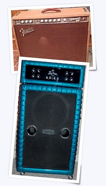
With roots extending back into the 1920s, commercial tube-type guitar amplifiers have been available since the 1930s. These ranged in power from a few watts to 50 or 60 watts in 1960, and selling points included number of controls and freedom from distortion.
Although tube amps fell somewhat out of favor during the mid to late 60s, many blues players continued to prefer their warmer sound, leading to the revival of their popularity during the Southern Rock era brought in by the Allman Brothers starting in 1969.
Solid-State Amps
In 1961, Standel released the first commercial hybrid guitar amplifier, model 82L15V, using a transistorized preamp and a 6DQ6 25 W power amp. Kay’s Vanguard amps (1962) were probably the first all-transistor guitar amps. In the mid-60’s several companies introduced solid-state amplifiers. Hartley Peavey’s first amps were solid-state, and unlike the more common tube models of the past, boasted output powers of 200 watts. Kustom (1966) found a sweet spot in the market with their high-power amps with rolled and pleated Naugahyde–upholstered cabinets. The Rolling Stones’ “Satisfaction” had topped the charts in 1965, and all of a sudden, “loud and distorted” was in. The rise of Acid Rock boosted the market for high-power solid-state amplifiers, and “solid-state distortion” was not considered objectionable for that style of music. Thus solid-state amplifiers enjoyed a strong demand throughout the 60s.
Pro Sound
The pro sound industry can be said to have mainly originated in the 1960s. At the beginning of the decade, most school and community theaters had minimal, if any, sound systems. By 1970, pretty much all newer systems were solid-state, either Bogen, University, or DuKane.
Sound systems in sports stadia in the 60s were almost exclusively used for speech, and often consisted of a Bogen, University, or perhaps Altec tube amplifier and too many re-entrant horn speakers. By the time I graduated from wake Forest University in 1970, the school had installed an Altec full-range horn cluster atop the field house, powered by solid-state amplifiers.
When festival-sound legend Bill Hanley first became associated with the Newport Jazz Festival, the electronics included McIntosh tube mixers and 200 W amplifiers. When Hanley provided the sound system for Woodstock in 1969, he used Shure solid-state mixers, Altec tube mixers, and 350 W McIntosh MC3500 hybrid power amplifiers. He also used Crown DC300 solid-state power amps for stage monitors. Most lounge bands were using Peavey or Kustom or similar solid-state powered mixers at that time.
The 1960s: Tube vs Transistor
The decade of the 1960s was a challenging time to be an electronics buff. Not only was a whole new technology being developed — two, if you count ICs as a separate technology — but new ways of designing circuits and new problems to be overcome (thermal runaway, crossover distortion, TIM distortion, etc.) required continually updating one’s education. Added to these was the public adoption of FM radio and stereo, plus ongoing arguments among the “experts” about the relative virtues of component stereo vs receivers, tubes vs transistors, and later, FETs vs BJTs. It was the best of times, and it was the worst of times.
Dr. Richard Honeycutt started repairing electronic devices in about 1965, earning his First-Class Commercial FCC license in 1969. He has worked part-time in broadcast radio engineering and audio electronics repair since 1968, in addition to fulltime work in acoustical and audio system design, plus a 20-year stint teaching electronics at the college level. His books Acoustics in Performance (Elektor 2018) and The State of Hollow State Audio (Elektor 2020) are available at Elektor.com.
This article first appeared in the special November 2021 edition of Elektor.


Discussion (0 comments)