
Tunable Valve Sinewave Generator
on
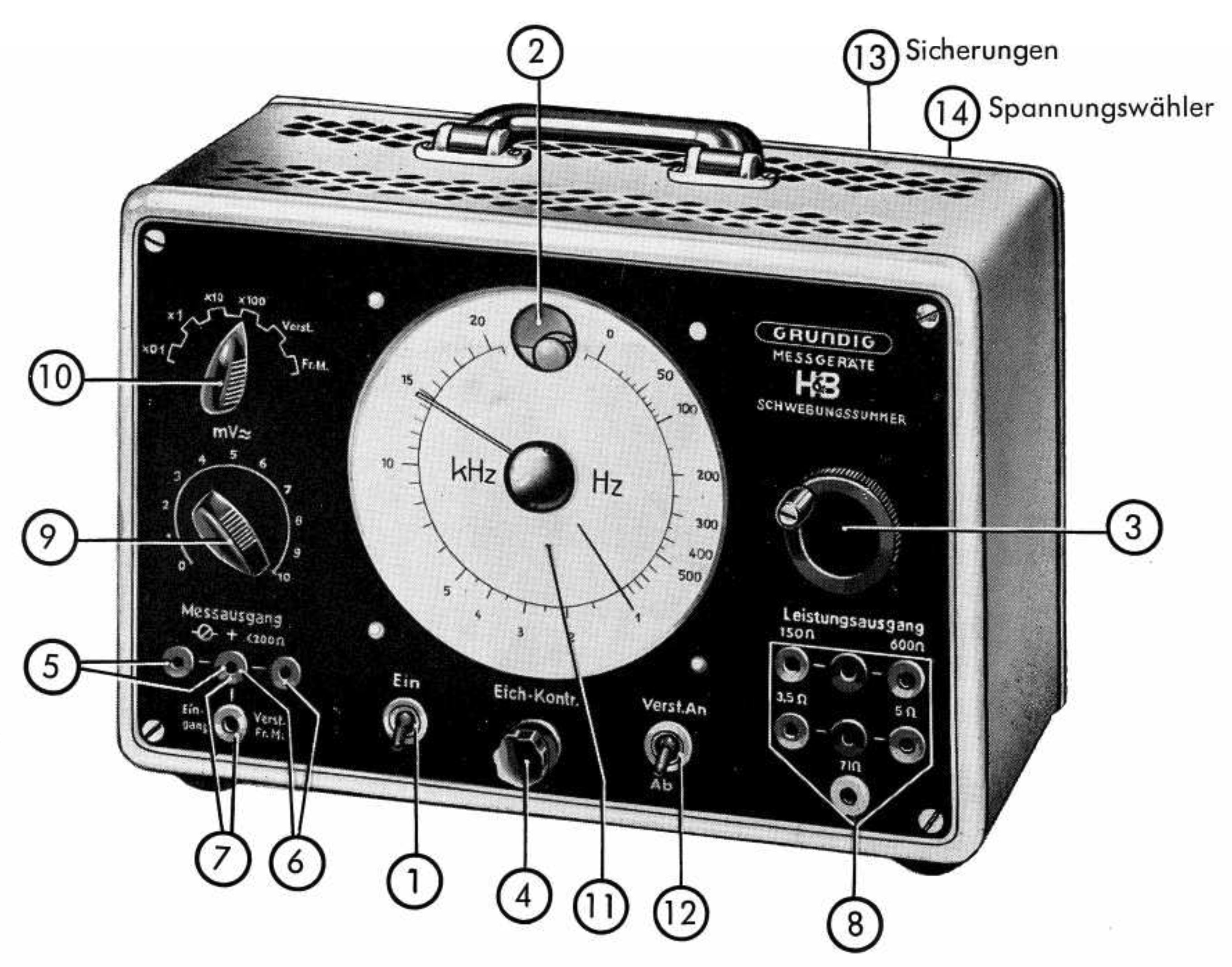
While preoccupied with these thoughts I happened upon the manual for the model 295A beat frequency oscillator made by Grundig/Hartmann and Braun (see Figure 1). This unit can be tuned in a single sweep over the entire audio frequency band from 20 Hz to 20 kHz without the need to change ranges, and such an enormous 1000:1 frequency ratio is not feasible with simple sinewave generators. And this brings us to the idea of heterodyning.
The heterodyne principle
Figure 2 shows the basic idea. Oscillator 1 creates a fixed frequency f1, here approximately 235 kHz. Oscillator 2, in contrast, is adjustable and generates a frequency f2 that can vary from 235 kHz to 270 kHz, which is less than a 20 % variation in frequency. It is easy to implement a narrow frequency range like this in a simple oscillator with the help of a variable capacitor.
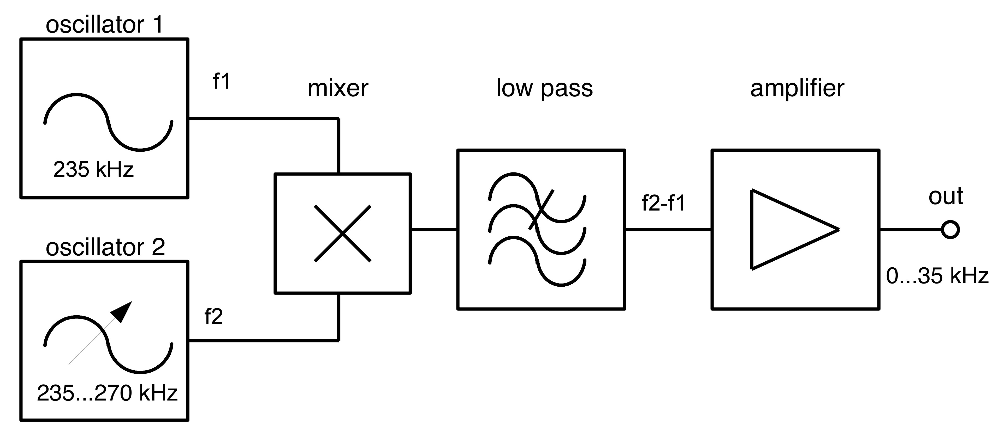
The output signals from the two oscillators are fed to a mixer. The output of the mixer includes, among other products, the difference frequency f1 – f2. The other products (the sum of f1 and f2 as well as the sums and differences of integer multiples of them) can be removed using a suitable low-pass filter. Finally we amplify the output signal to provide a low-impedance source. It is also possible to use the heterodyne principle to build tunable RF oscillators operating up to the GHz range.
The original
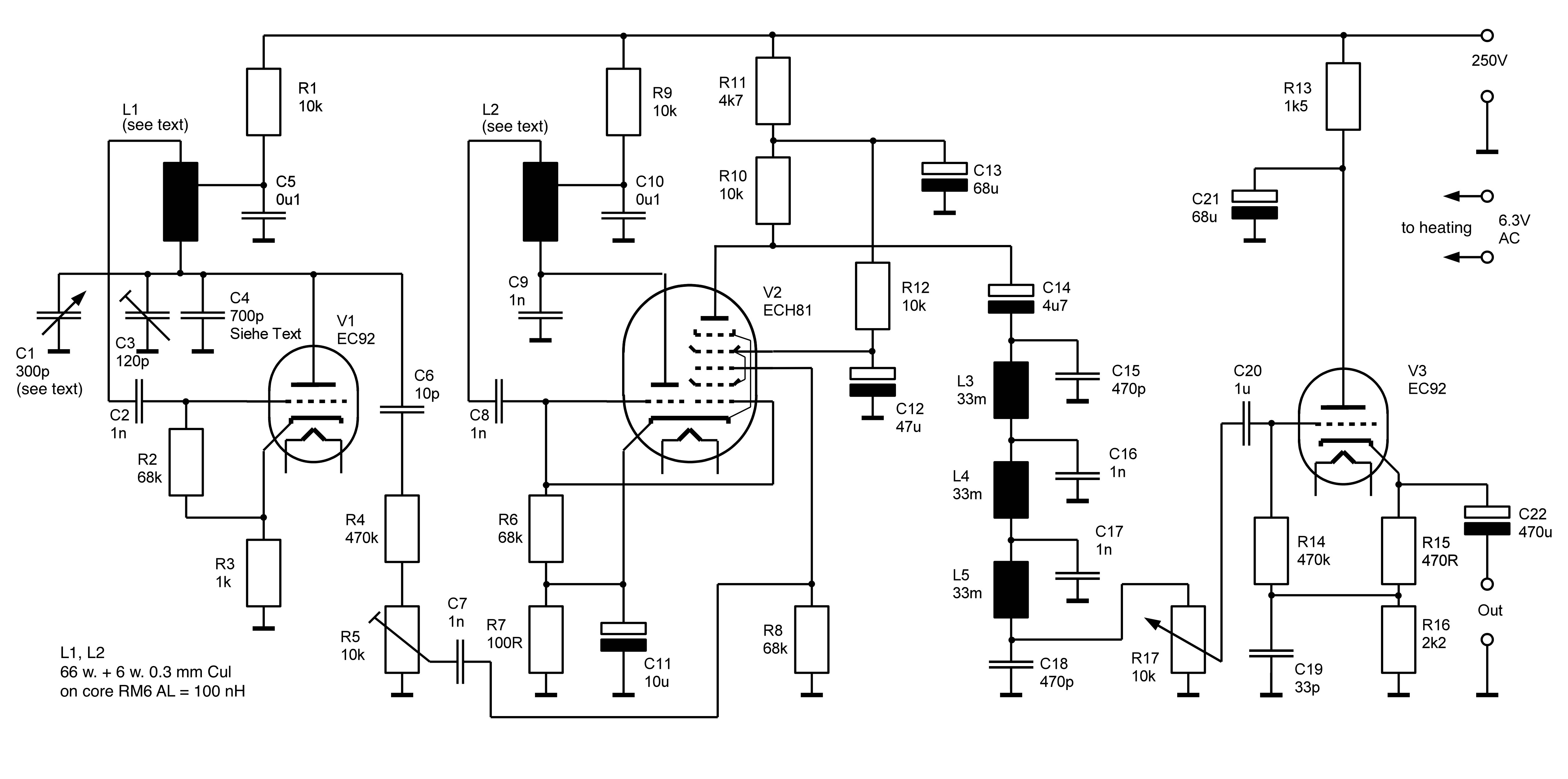
Figure 3 shows an extract from the circuit diagram, including the two oscillators, the mixer, the low-pass filter and the final amplifier stage. The valve labelled ‘Rö2’ is responsible for generating the fixed frequency. Its anode is connected to a resonant circuit which determines the frequency of oscillation, and there is a transformer to provide feedback to the grid electrode.
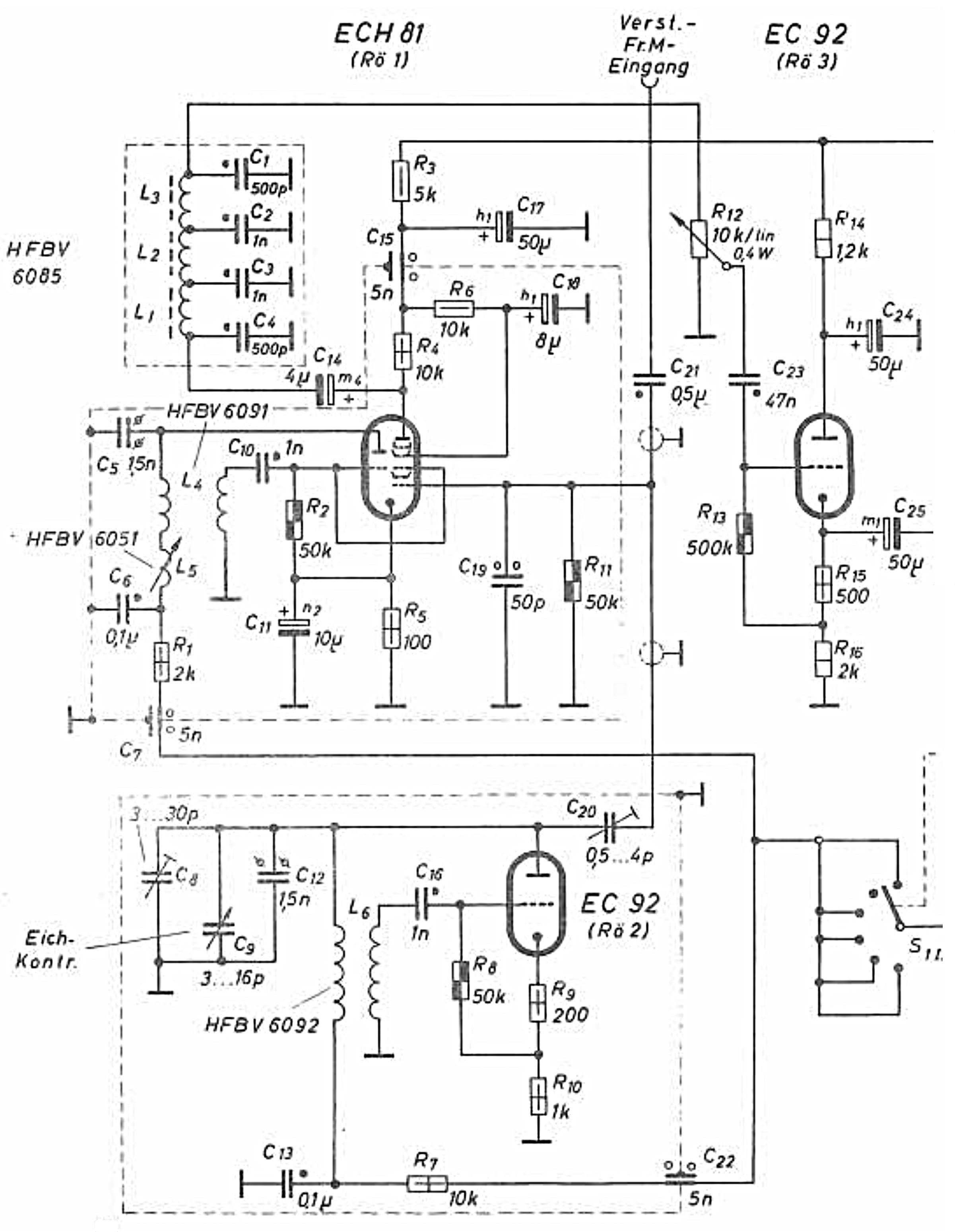
The variable frequency is generated in the same way using the triode section of an ECH81 (left-hand part of the valve labelled ‘Rö1’). The frequency is adjusted using variable inductor L5. The outputs from the two oscillators are then taken to grids G1 and G3 of the heptode section of the ECH81, and the mixer products appear at the heptode anode.
The low-pass filter is constructed from L1, L2 and L3 along with C1, C2, C3 and C4. The filtered output signal is then passed through a potentiometer to allow adjustment of the signal level to the valve labelled ‘Rö3’, which is configured as a cathode follower. The low-impedance sinewave output signal is available at the cathode of this valve.
My cover version
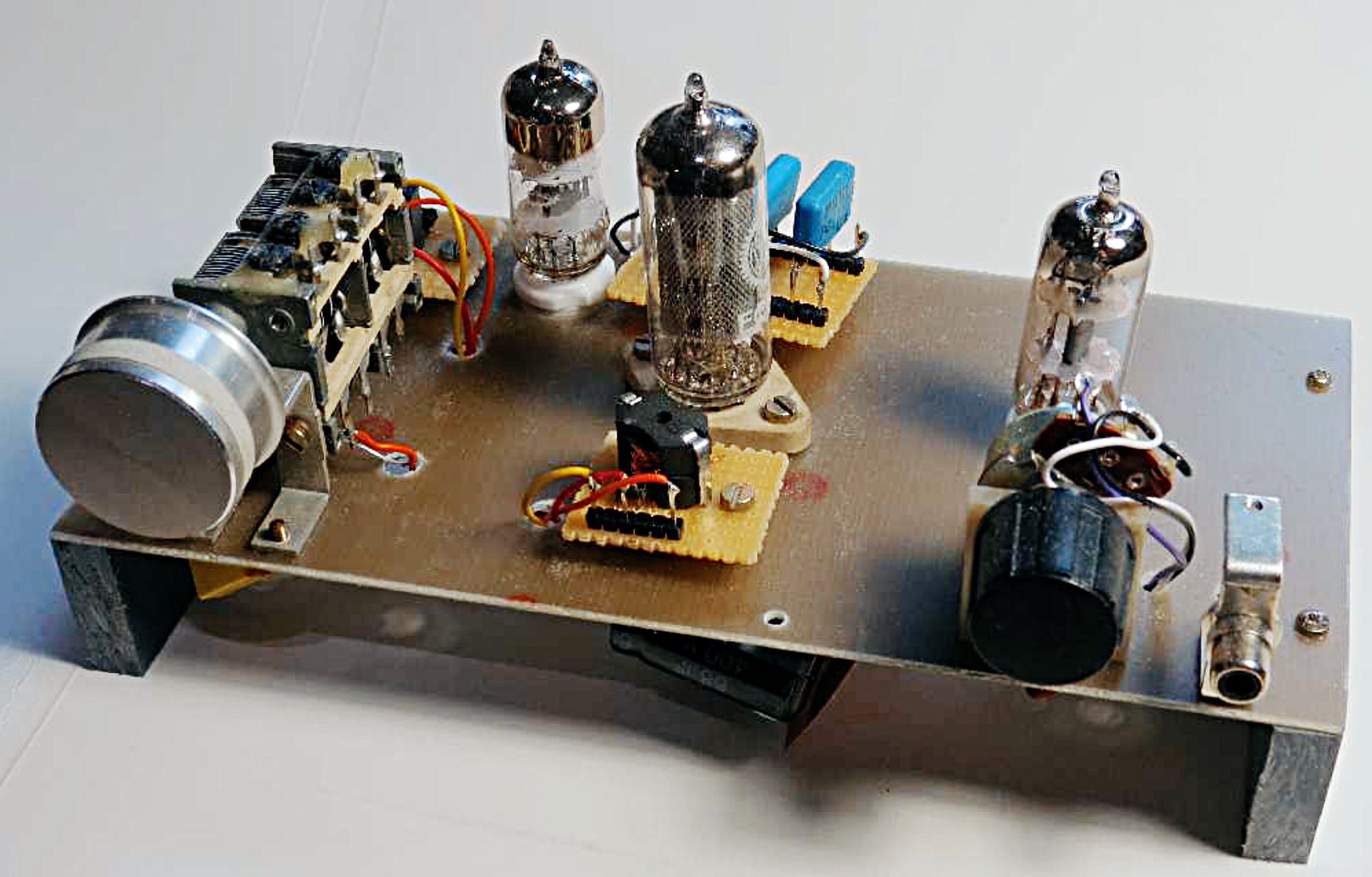
To make constructing a version of this unit easier I tried out a couple of modifications. Instead of a variable inductor to adjust the frequency I used a variable capacitor; and I modified the feedback circuit in the oscillators to use tapped inductors instead of transformers. My ‘free form’ design built on the bench for testing is shown in Figure 4.
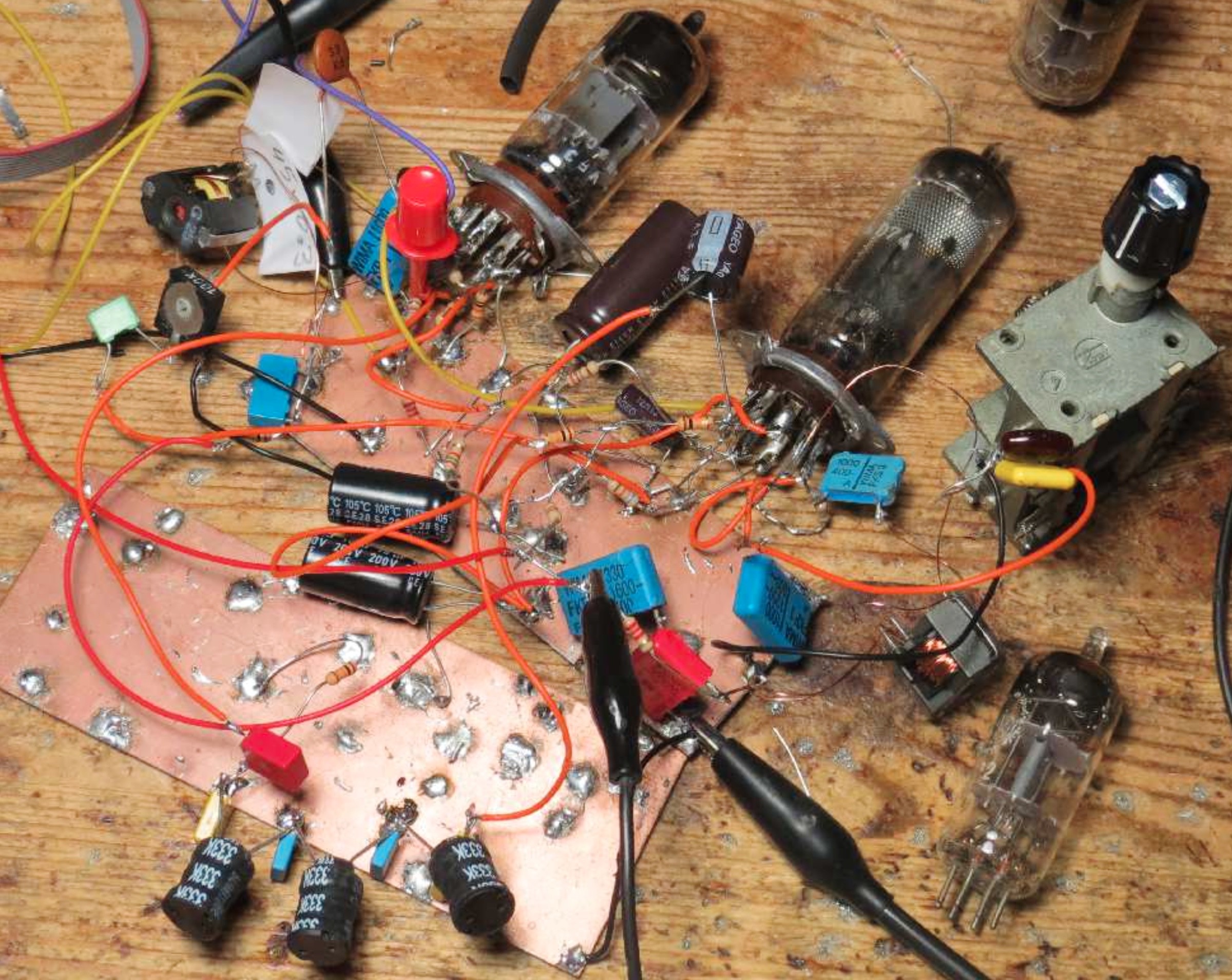
Figure 5 shows the complete circuit diagram for your edification. Triode V1 implements the variable-frequency oscillator, and its output signal passes via a potentiometer to grid G3 of the mixer valve V2. The triode section of V2 is used to form the fixed-frequency oscillator, and its output it taken to grid G1 of the heptode. The mixer output appears on the heptode anode.
Measurements
In order to check the basic operation and signal quality of my final prototype (see Figure 6) I made a few measurements.
I measured a signal amplitude of approximately 200 Vpp on the oscillator anodes; of particular interest is of course the anode signal on the mixer valve, which is shown in Figure 7.
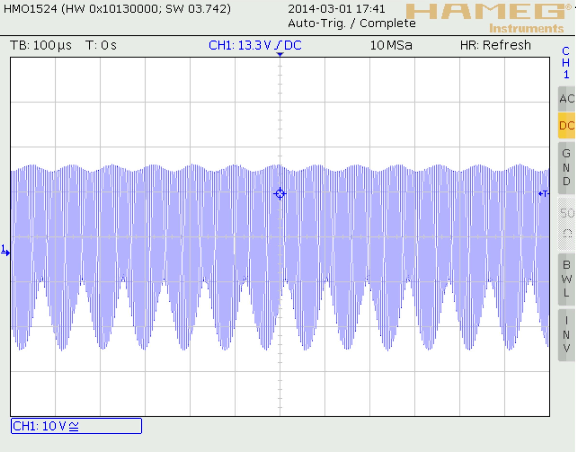
The rapid oscillations are the two high-frequency tones, while the lower envelope represents the generated sine wave signal: it is this that we subsequently extract with the low-pass filter.
Figure 8 shows the spectrum of the anode signal on the mixer valve. It is easy to see the many product tones generated from the two oscillators. Adjusting potentiometer R5 alters the amplitude of the output signal, but at the same time it also alters the drive level of the mixer valve.
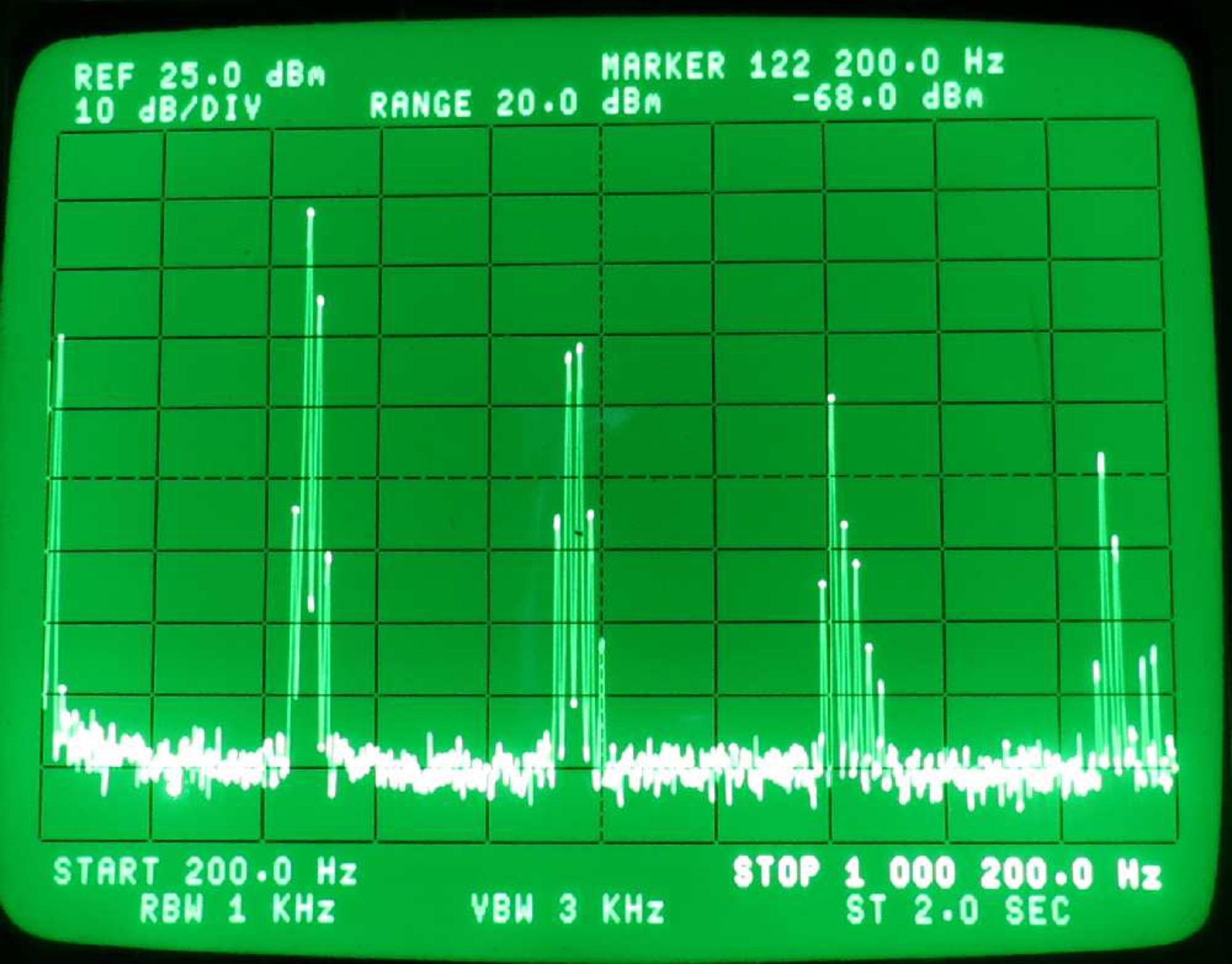
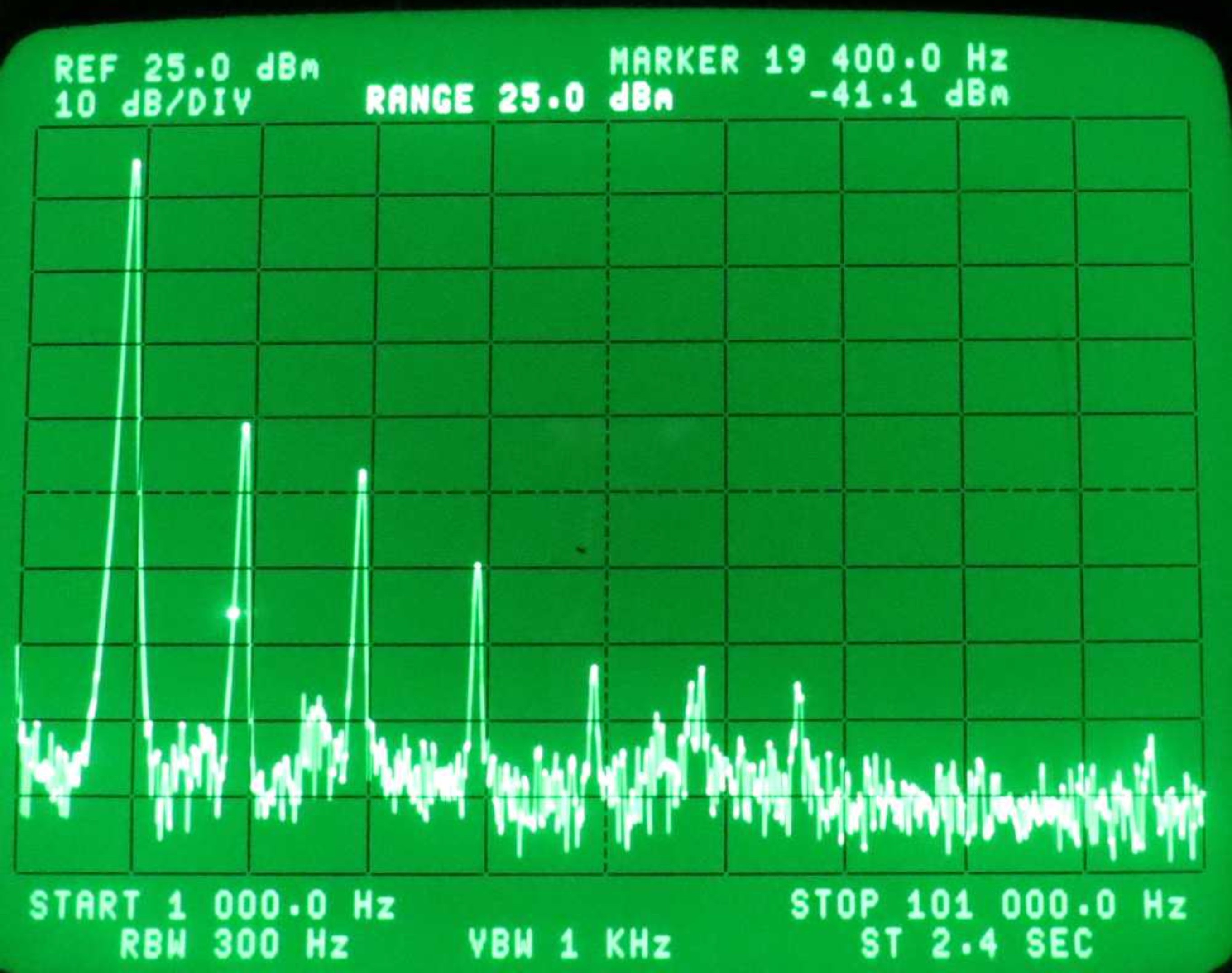
If, for example, we set R5 so that a signal amplitude of 8 Vpp appears on grid G3, we obtain an output amplitude of around 7 Vpp. At such a high output level we of course get considerable distortion in the output signal: the spectrum is shown in Figure 9. The second harmonic is only about 35 dB below the fundamental, and the distortion factor is not particularly impressive at over 1%.
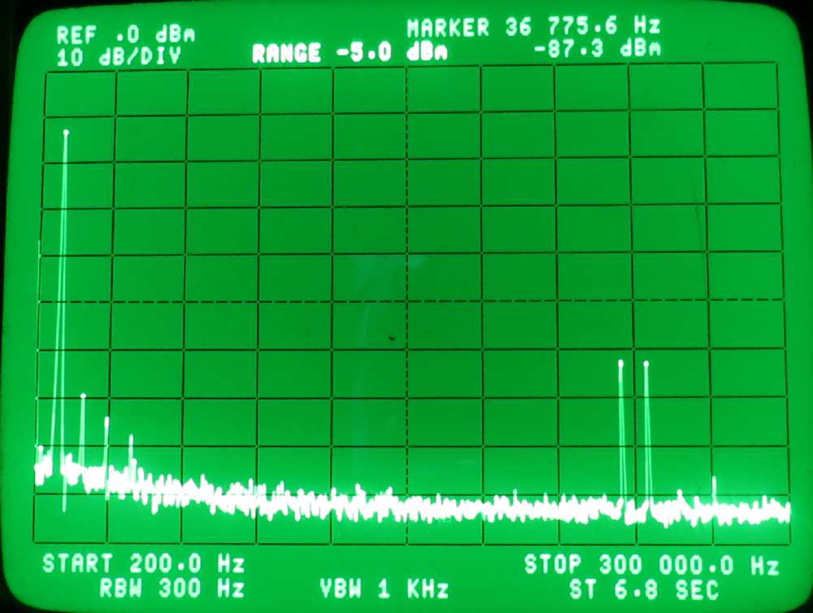
If, on the other hand, we adjust the amplitude of the signal on G3 to just 1 Vpp, we obtain an output signal amplitude of 2 Vpp whose spectrum, shown in Figure 10, looks a lot healthier. The second harmonic is now more than 50 dB below the fundamental, and the distortion factor is down to about 0.3 %, which is much more satisfactory. There are still residual tones at 235 kHz and 250 kHz, which are being capacitively coupled through the low-pass filter to the output signal. This could be mitigated by improving the screening of the high-frequency parts of the circuit.
So in conclusion we can see that it is possible to build a useful adjustable sinewave generator covering the whole of the audio frequency range using just three valves and a handful of other components.
Postscript: Perhaps not all hobbyists are familiar with the classic ‘0V2’ RF terminology used by radio amateurs. The first number gives the number of RF preamplifier stages before the detector, while the number after the ‘V’ gives the number of audio amplifier stages. Thus a type ‘0V2’ receiver is an ‘Audion’ design with one valve, no RF preamplifier stages, and two audio amplifier stages.
Enjoy learning about the sinewave generator? Want more great Elektor content?
Take out an Elektor membership today and never miss an article, project, or tutorial.
Discussion (8 comments)