
Wearable Wi-Fi Gadget
on
The project was abandoned, and it would have faded into oblivion if — fast forward to a few months back — I hadn’t had an urgent need for an ESP8266 module for my home automation experiments. Searching through boxes filled with stuff that might come in handy someday, I stumbled upon my wearable ESP8266 prototype. And, as I was obsessed with ESPHome [1] at that time, I immediately knew that I now had the tools to finally create the software for this board.
Wearable NodeMCU-Like Circuit
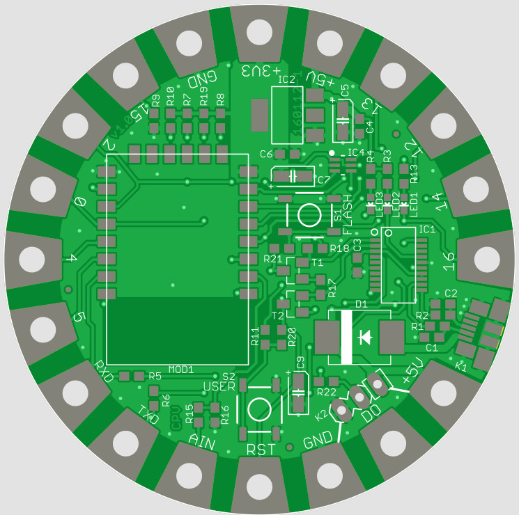
The schematic of the board (Figure 1) is basically a NodeMCU with the CP2101 USB-to-serial bridge from Silicon Laboratories (a.k.a. Silabs) replaced by the much cheaper FT231XS from FTDI. Also, a port for an addressable WS2812-based LED string (NeoPixels if you prefer) has been added.

As the wearable gadget is almost a NodeMCU, everything that follows is also valid for a normal NodeMCU module. The presented software works equally well too.
The available GPIO ports and power supply are brought out on special pads with large holes placed in a circle at the edge of the round board. These pads are intended for use with conductive thread, but you can, of course, also solder wires to them or use crocodile clips.
Power for the circuit is supplied by either the micro-USB port or by connecting an external 5V power supply to one of the 5 V pins. This is useful when using long LED strings as they demand more power than a normal USB port can provide. A high-capacity USB power bank is also an option. Note that the LED interface is for 5 V strings. Also note that the 5 V input does not have reverse-polarity protection.
Software Design with ESPHome
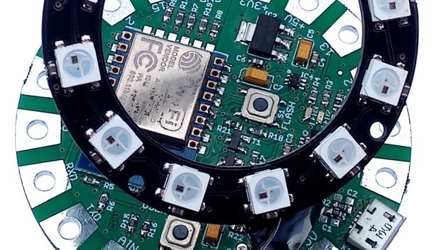
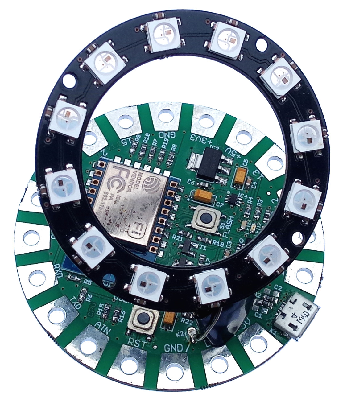
For my experiments, I connected a ring-shaped string of twelve WS2812 LEDs to port K2, see Figure 2. Of course, you can write the software for this board from scratch, like my former colleague planned to do, and probably had to as there was not as much ESP8266 code available as there is today, but adopting an open-source project like ESPHome saves you a huge amount of work.
I’ve said it before, and I will repeat it once again, ESPHome lets you create a connected application for the ESP8266 or ESP32 featuring over-the-air (OTA) programming, fallback hotspot, webserver user interface, and interfaces for over 200 devices in minutes. Really. Refer to [1] for more details.
ESPHome uses a modular approach where ready-made code blocks are combined to form an application. The blocks required by the application are listed in a configuration file, the so-called YAML file (YAML comes from ”Yet another markup language” and is not a language but a set of text file formatting rules to specify parameters and values [1]). Each block is configured individually, to specify for instance the GPIO pin(s) it should use, or the communication protocol or its type.
The configuration file is read by ESPHome and turned into C++ code, which is then compiled into an executable that can be programmed into the module’s flash memory. Once you have understood how to compose a configuration file, you’re in business. Please refer to [1] for more details.
A Close Look at the Configuration File
The YAML configuration file (Listing 1) starts with the obligatory esphome: a section to specify a name, the MCU used (ESP8266) and the board type (NodeMCU).

Specifying the logger: option activates the status output on the serial port. The api: option enables easy integration with the free and open-source home automation controller software Home Assistant (see [1]). And ota: is for over-the-air device programming (from e.g. Home Assistant), which is very practical as it removes the requirement of having a physical connection to the device.
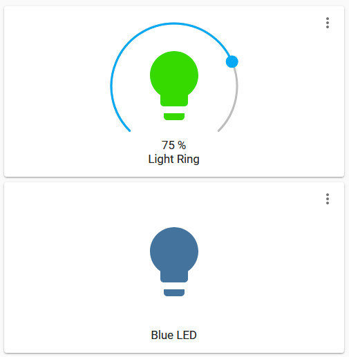
Next comes the meat of the application, starting with the specification that GPIO16 must be an output. This is needed if you want to use the LED that is connected to it as a light device, which is interesting - as lights have different options as for instance switches (Figure 3).
Wearbale Lights
As lights I defined the blue LED on GPIO16 and the LED string. The latter is handled by the neopixelbus platform, which has a few options that must be specified like the length of the string and the port it is connected to. In this case the port is GPIO2 which allows the use of the ESP8266_UART1 method. Actually, when specifying this method, you don’t have to specify GPIO2 as it is implied.
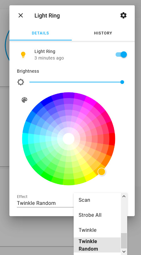
Lights can have effects, and ESPHome has a few built in that you can use (if your light supports them, of course). It goes without saying that you can also program your own light effects. I specified most of the built-in effects for the LED ring. Effects can have parameters but without them default values will be used. Home Assistant lets you choose which effect is active (Figure 4). I like the random twinkle effect.
Other In- and Outputs
The unused GPIO ports are declared as switches so you can toggle them on and off from within Home Assistant. In home automation, a switch is a device that is controlled by the system (e.g., a relay). A switch that is controlled by the user (or occupant) is a binary sensor. GPIO0 has a pushbutton connected to it and therefore it is specified as a binary sensor.
Finally, the board has an analogue input on pin A0 with a voltage divider in front of it (R15 & R16), which explains the multiplication factor of 3.2 that converts the divided input voltage back to volts. The maximum input voltage is 3.3 V.
Build a Wearbale Social Distancing Alarm
ESPHome features automation and you could, as an example, add a proximity sensor to the board to change the colour of the LED ring depending on what the sensor sees. This way the board could for instance be a social distancing alarm. It can also just be a decorative electronic pin or brooch; let your imagination go wild.
An interesting possibility here is to use Home Assistant. With a few of these wearable ESP8266 boards integrated in Home Assistant fancy lighting effects (e.g., for Christmas) can be created. But, even though Home Assistant is optimised for home automation, it can also do other things, like controlling a game at the birthday party of your toddler. Stick a board on every kid and use Home Assistant to create and control teams or decide which candidate may answer a question or who is ‘it’ when playing tag. I am sure that with a bit of creativity lots of fun applications can be invented. The design files can be downloaded from [2].
Wearbale Wi-Fi Gadget: Component List
Resistors
- All 5%, 50 V, 0.1 W, 0603
- R20 = 0 Ω
- R1,R2 = 27 Ω
- R11,R13,R21,R22 = 470 Ω
- R3,R4,R5,R6 = 1 kΩ
- R7,R8,R9,R10,R17,R18,R19 = 10 kΩ
- R16 = 100 kΩ
- R15 = 220 kΩ
Capacitors
- C1,C2 = 47 pF, 0603
- C3,C4 = 100 nF, 0603
- C6 = 1 µF, 0603
- C5,C7,C9 = 10 µF, 16 V, Case-A
Semiconductors
- D1 = MBRS540
- IC4 = 74LVC1T45GW
- IC1 = FT231XS
- IC2 = LD1117AS33
- LED1 = LED, blue, 0603
- LED2 = LED, yellow, 0603
- LED3 = LED, red, 0603
- T1,T2 = BC847C
Miscellaneous
- K1 = Micro USB Type B receptacle, bottom mount
- K2 = 3-pin pinheader, 0.1" pitch
- S1,S2 = Tactile switch, 5.1 mm x 5.1 mm
- MOD1 = ESP-12F
- PCB 160112-1
Discussion (0 comments)