
Why Study 8-Bit AVR Microcontroller Architecture?
AVR Architecture and Assembly Language
AVR architecture refers to internal structure of AVR microcontrollers, or the ‘core’ of the AVR. Figure 2 shows the block diagram of an ATtiny85 AVR microcontroller taken from its datasheet, with the AVR core highlighted in a red box. Outside of the core are peripheral devices specific to this particular AVR part. The core, or central processing unit (CPU), is what is common between between all 8-bit AVR microcontrollers. Strictly speaking, there are some differences between cores across different AVR parts because there are actually different AVR CPU versions. One could also argue that SRAM and Flash program memory are not part of the core.The programmer’s model of the AVR CPU consists of 32 general-purpose registers, the status register, program counter, stack pointer, and memory map. Any program written for the AVR accesses or manipulates these items, whether written in C, C++ or assembly language. This is because all AVR programs end up as binary machine code in the Flash program memory of the microcontroller. Machine code usually converts to assembly language directly, that is, one machine code instruction can be written as an equivalent assembly language instruction. For example, if we were to find the following binary machine code instruction at a Flash program memory address in an AVR:
1001 1010 1011 1100
We could find out what the equivalent AVR assembly language instruction is, which is the following:
sbi DDRB, DDB4
The AVR instruction set manual tells us that the SBI instruction means Set Bit in I/O Register. Note that the Atmel/Microchip convention is to write assembly language instructions in lower-case in code listings, but in upper-case in text. What SBI does is set a particular bit, in this case bit DDB4, in a particular I/O register, in this case I/O register DDRB. What we have just done by converting a binary machine code instruction to its assembly language equivalent is called disassembly.
Programs written for AVR microcontrollers in the C programming language are also converted to assembly language before finally being converted to machine code. As an example the following line of C code sets bit DDB4 in register DDRB:
DDRB |= (1 << DDB4);
This line of C code is converted by the C compiler to the following line of assembly language:
sbi DDRB, DDB4
This particular example was chosen to match the previous disassembly example and happens to convert from one line of C code to one line of assembly language code. In other cases a line of C code may convert to more than one line of assembly code.
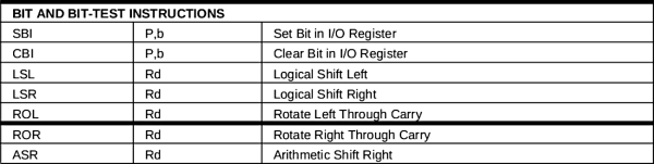
Assembly language instructions consist of an opcode in mnemonic form. One or more operands may follow, depending on the instruction. Figure 3 shows an excerpt from the instruction set summary taken from an ATtiny85 datasheet. The instruction set of a microcontroller consists of all of the binary machine code instructions that the microcontroller architecture can execute, or all of the assembly language instructions that it can execute.
Debugging Optimized C Code
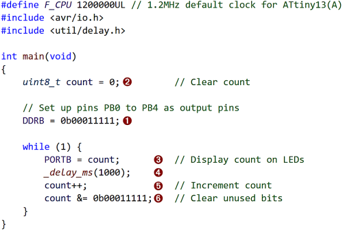
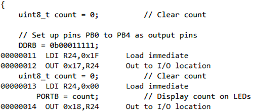
Now that we know a bit about how assembly language fits into the picture, it is time to get back to the original example of debugging optimized C code. Figure 4 shows a trivial C code example. Debugging of this code is done in Microchip Studio with an Atmel-ICE debugger attached to the external hardware. When stepping through this code that was built using default compiler optimization settings, something odd happens. Code execution starts at the second line of code in main(), marked 1 in the figure. When stepping to the next line of code, execution jumps above this line to the first line of code in main() marked 2. After this, the order of execution continues as expected in the while(1) loop with the lines of code executing from 3 through to 6 in order. The same code executes as would normally be expected when it is built with compiler optimization set to none. That is, the count variable is initialized first, followed by the value written to DDRB.To understand what is happening in the optimized code, we can open the disassembly window in Microchip Studio. Figure 5 shows just part of the code from the disassembly window. At the top of this figure is the opening brace of the main() function, followed by the first line of C code in main(). After this is the second line of C code in main(), followed by the two lines of assembly language code that it was converted to. After these lines of code is the same first line of C code from main(). The reason that it is repeated here is because this is the way the C compiler put the code together using the optimization settings passed to it. The first time that this line of code appears is in effect just a listing of this code. It is actually implemented the second time it appears. This is confirmed by the line of assembly language code that it was converted to appearing below it.
As can be seen even in this trivial example, it is necessary to understand AVR assembly language in order to read and understand the code in the disassembly window. As already mentioned, to understand assembly language code, the basics of the AVR architecture must also be understood.
Read full article
Hide full article
Discussion (1 comment)