
Pulse-Width Modulation (PWM) Measurement with a PIC Microcontroller
on
Although programming an Arduino is simpler than a Microchip Technology PIC, the latter was more precise and accurate in calculating the timing of a pulse-width modulation (PWM) signal, due to its architecture. The challenges to be faced are certainly harder; but at last, they will enrich the experience of those who enjoy coding. The proposed instrument can simultaneously measure high and low pulse durations and also measure the period, all with the resolution of 1 µs for pulse durations from 10 µs to 65,535 µs for PWM signals with frequencies from 7.63 Hz to 50 kHz.
The technique of varying the pulse duration over time is called pulse-width modulation (PWM), a modulation that originated in telecommunications but has also found use in the digital-analog world to vary the average voltage or current whose value depends on the ratio of the duration of the positive pulse to the entire period, a ratio that is called duty cycle. PWM is used to regulate voltage in switching power supplies, for motor control, for servo actuators, and even for the output of some sensors. For these reasons, most modern microcontrollers have one or more PWM outputs. Some transducers, such as, for example, acoustic distance sensors, have a digital pulse output whose duration is proportional to the amplitude of the signal. The purpose of this project is not to generate PWM signals, but to measure their pulse duration with good accuracy.
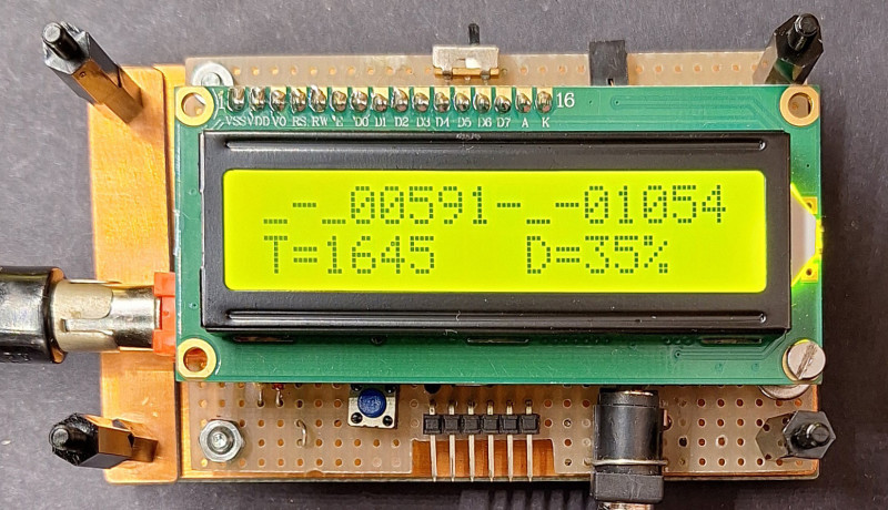
In this article, I will describe a version that uses the PIC16F628 to measure the durations of the upper and the lower parts of the pulses, as well as the period, as visible in the introductory photo. If you also want to calculate the duty cycle as a percentage, you will need a PIC16F648 because the project requires division. The program only needs a few additional instructions, but the code exceeds 2 K words, and the F628 has just 2 K of flash memory. Source programs and compiled HEX files are provided for both versions. The rest of the hardware remains exactly the same.
PWM Measurement and the PIC Microcontroller
Why this choice? In my case, I had already done something like this several years ago, when I mainly used PICs in my projects, then switched to developing with Arduino IDE and MicroPython. In PIC microcontrollers, the internal clock is one-fourth the frequency of the quartz oscillator, and all instructions are executed in one clock, except for program branches. With a 16 MHz crystal, the internal clock is 4 MHz, so the instruction execution time is only 0.25 µs.
The PIC16F628 is a Microchip microcontroller with Reduced Instruction Set Computer (RISC) architecture that works on 8-bit data, but its 35 instructions each occupy a 14-bit word; in our case the flash memory is 2K words. This PIC, among its many I/O functions, also has event capture on the CCP1 pin (PB3), at which it stores the contents of Timer1 in two registers, CCPR1L and CCPR1H. Something similar is also there for the Arduino UNO’s ATmega328P, but the choice of a PIC leads to a much simpler, more compact system with much lower power consumption.
Of course, those used to working with Arduino will face greater difficulties in designing anything with PICs. It’s not as easy to find pre-made boards or the many libraries available for Arduino to manage the devices used. In my opinion, working with Arduino only doesn’t allow delving very deeply or even knowing exactly what one is doing at all.
Many Arduino users do nothing more than replicate project connections, now made with Fritzing figures, and with pictures of the components arranged on breadboards, and do not know how it all works (even though it often does not work at all because of uncertain or incorrect connections).
The compiler used for PICs is less user-friendly than the Arduino IDE and the libraries available are much scarcer, for example there is no pulsein() function to measure the duration of a pulse. For these reasons, the designer must go deeper into the operation of microcontrollers, as I also did to do this project, where I had to study the datasheet to understand the operation of timers and CCP capture.
The mikroPascal compiler, which I used to develop the programs with the PICs, is free only for programs whose code is smaller than 2K words (1 word = 14 bits), which, in this case, was not exceeded also because this is the flash size of the PIC used while the RAM is only 224 bytes. With these limits, not much can be done: Using, for example, a float division easily exceeds the memory limit. But compilation is much faster than with Arduino, and certainly the code produced is also more compact and optimized.
The program was written in Pascal, using a powerful cross-compiler on Windows PCs: the mikroPascal PRO for PIC, version 7.6.0. A full version can be downloaded at the MIKROE website. In this first version of the program, the code is shorter, so you can compile it without problems. Those more familiar with C or Basic can download these compilers and translate the program into the new language. If no changes are made to the program, you do not even need to download the compiler, but just need a PIC programmer using the already compiled hex file, PWMmeter.hex.
A further version of the program that calculates the duty cycle has also been developed, but, due to floating-point division, it requires more flash memory and a PIC16F648. In this case, if you have not purchased the compiler license, you must program the chip with the HEX file provided with this project. Both of these microcontrollers are pin-to-pin compatible.
Measurement of Pulse Duration
Some microcontrollers with a built-in BASIC interpreter, such as Stamp, Picaxe or BasicX, use a special routine (PULSIN) to measure pulse duration, but cannot measure short pulses because of their relative slowness. Arduino boards use the pulsein(pin, level, timeout) function to measure the duration of a pulse, high or low level, with microsecond resolution. For longer times there is the pulseInLong() function, which uses the interrupt and measures times from 10 µs to 3 minutes. Both functions return an unsigned long.
The program uses two interrupts: Timer0 for sampling time while the second interrupt source is generated on CCP (capture/compare/PWM) capture events on the rising and falling edge of the pulse and the respective times are counted in Timer1.
Timing With Timer0
Timer0 generates an interrupt that is used to sample measurements and display them on the LCD every 50 events, corresponding to about 0.5 seconds. Timer0 is an 8-bit TMR0 counter, preceded by an 8-bit programmable divider called a prescaler.
The program selects the internal clock, which has a frequency equal to one quarter of the crystal frequency: 16 MHz /4 = 4 MHz. If we set the prescaler with the highest value (1:256), Timer0 will have as input a frequency of f1 = 4 MHz / 256 = 15.625 kHz, with a period of 64 µs; loading 100 into the counter will result in an interrupt every 156 (256-100) pulses of frequency f1, corresponding to a period of 156 × 64 = 9984 µs (about 100 Hz).
The Timer0 interrupt is generated when the timer/counter in the TMR0 register goes into overflow from 0xFF to 0x00, which sets the T0IF bit. This interrupt generates the clock that is used to sample the measurements and present them on the LCD, every 50 events, corresponding to about 0.5 s.
Event Capture With Timer1
The program, after the rising edge on pin PB3, changes the capture mode for the falling edge, and vice versa. The pulses can be low high low level, which we will call LoHiLo, or, inverted, HiLoHi, as shown in Figure 1. The pulse type is selected by Dip1: OFF = LoHiLo, ON = HiLoHi, and its setup is read by the program at startup.
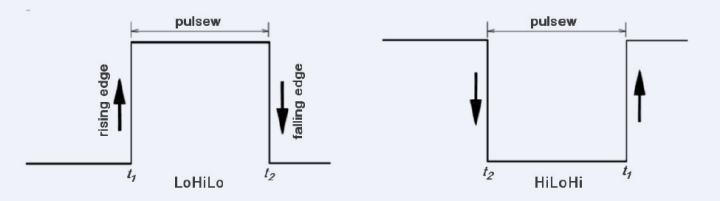
For LoHiLo type pulses the program sets the CCP1CON := $05 register with capture on rising edge. When this event occurs the interrupt routine saves the contents of the CCPR1L and CCPR1H register pair which will then be transferred to t1. Then the CCP1CON := $04, setting the capture on falling edge, at whose event the register pair CCPR1L and CCPR1H will be read again, which will then be transferred to t2, as seen in Figure 1. The pulsew time is derived from the t2-t1 difference.
For HiLoHi-type pulses, things are similar, but you start with the falling edge (t2) and end with the rising edge (t1), in which case the pulsew time = t1−t2. Timer1 has a 16-bit counter, preceded by a 2-bit prescaler.
The internal clock of 4 MHz is also used here. With the prescaler = 1:1 there is a resolution is 0.25 µs, which is excessive if we consider a normal crystal, so the 1:4 ratio with a resolution of 1 µs was used. Therefore, the system measures pulses of duration between about 10 µs up to 65,535 µs. Below 10 µs, it does not work, because there are several instructions in the interrupt routine, and this requires some execution time. If you want to measure longer times, with a resolution of 2 µs, you have to use the 1:8 ratio. In this case, the times should be multiplied by two after converting the variables to long integers.
The bespoke new, bigger version of the original program can measure the two durations at the same time; therefore, you can calculate the PWM period and also the duty cycle. In this case, the program selects the capture for the rising edge, stores the time in t1, raises the firstcre flag to distinguish this edge from the last one, then sets for the falling edge and puts the time in t2, and sets for the next rising edge which it will put in t3, as seen in Figure 2. At the third edge, the interrupt routine sets the datok flag to indicate that times t1, t2 and t3 have been measured.
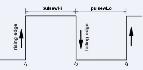
Therefore, it calculates:
pulsewHi = t2−t1, pulsewLo = t3−t2, period = pulsewHi + pulsewLo
Duty cycle requires operations with float variables (real in Pascal) that exceed the flash memory limits of the 16F628, but we can do them with a calculator:
Period = T = pulsewHi + pulsewLo
Duty cycle: D = pulsewHi / T × 100 [%]
Comparison With Arduino pulseIn()
For comparison, just for a LoHiLo pulse, I also wrote a small program for the Arduino Uno:
// program pulseintest
#define pulsein 4
void setup() {
Serial.begin(115200);
pinMode(pulsein, INPUT);
}
void loop() {
unsigned long duration = pulseIn(pulsein, HIGH);
Serial.print("Pulse High [us] = ");
Serial.println(duration);
delay(500);
}
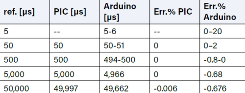
To check the times, I used my own crystal-based device with programmable divider and square wave output as a reference; in Table 1 are the results compared with that of my PIC system. As can be seen, the PIC system is very accurate.
The Circuit Schematic
Figure 3 shows the system’s schematic. Using an LM7805 (a 78L05 will also do), the system should be powered as an Arduino UNO, that is, with a voltage from 7 V (optimum value) to 12 V, but it consumes, without backlight (W2 off), less than 10 mA, of which a current of about 3 mA is drawn by the regulator. A much simpler system is to use three common 1.5 V batteries. In this case, what might be more critical is the LCD, which has a rated supply voltage of 5 V, but similar devices usually run on 4.5 V as well.
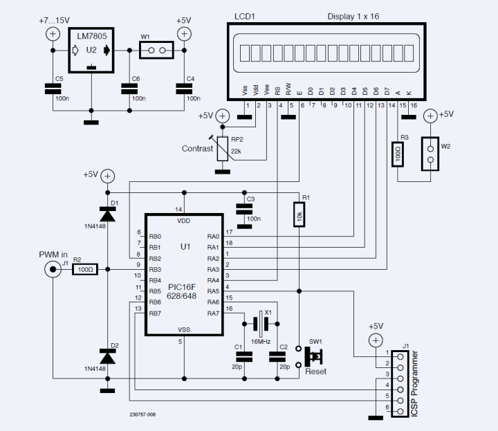
As a display, I used a common two-line 16-character LCD with an HD44780-compatible parallel interface. Jumper W1 is used to avoid power supply conflicts and must be removed if you program the chip with the PICKIT. Jumper (or switch) W2 is used to turn off the backlight and save power.
The Prototype
Figure 4 shows the arrangement of components on the perforated matrix board used to make the prototype. The LCD has been removed to show the components mounted underneath.
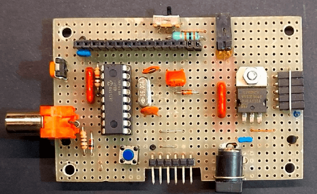
emale strip connector on the right is not in use
On the top, a small switch (W2) is seen — it turns off the display backlighting, while on the left, an RCA connector used for PWM input is mounted, and, below, present is a 6-pin connector for chip programming, which is compatible with the PICkit in-circuit programmer. If you have a PIC programmer with ZIF sockets, this connector is not required, but you need to remove the PIC from its socket to program it. Next to it, still at the bottom, you can see the power connector. The board size can be further reduced, as it was recycled from a previous project. The 5-pins female strip connector on the right is not in use.
The Program
Most of the program has been described above. The outputs on the LCD are more basic than Arduino’s LiquidCrystal library functions, and the messages must be strings or arrays of characters, so it is necessary to convert the variables to strings and remove any leading spaces.
The most important work is done by the interrupt routine. In the first part, it checks whether the interrupt is caused by Timer0 overflow, in which case INTCON, T0IF = 1, raises the int0flg flag, which is used for timing. It then reloads the number 100 into the counter so that it triggers an interrupt after 156 pulses and resets the interrupt INTCON and T0IF flags to 0.
The second part, which is more complex, is to handle the capture of the rising and falling edges and save the contents of the two capture registers, CCPR1L and CCPR1H, to variables t1, t2 and t3, corresponding to the first rising edge, the falling edge, and the second rising edge. When all these three times have been captured, the datok flag is set, which will be used by the program to calculate the durations and period.
The times, expressed in µs, relating to the PWM’s upper part, indicated with '_-_' and the lower part, indicated with '-_-', are printed on the first line. The PWM period, i.e. the sum of the two times, is printed in the second line.
In the absence of a signal, the display does not show anything. You can see the complete code in Listing 1. (Editor's note: Listing 1 is available at the end of this article.) This program occupies 1,236 words of flash memory (65%) and 74 bytes of RAM (37%), and compilation was done in 187 ms.
Program Version With Duty Cycle Print Option
In this case, you need a PIC16F648A, which is similar to the F628, but has 4K words of flash memory. As already mentioned, to compile this version you need to purchase the program license, which lifts the 2K-word limit. But, the already compiled hex file for the PIC16F648 is included in the package for this article and can be uploaded to the PIC straight away.
The program prints pulsewHi [µs], pulsewLo [µs], period [µs] and dutyc [%] on the display. Unfortunately, the floating-point division gave me memory problems in the compilation, the reason being that even the PIC16F648 is not very suitable. I overcame the inconvenience by converting the percent duty cycle to an integer, losing the decimal part.
Comparative Tests
Figures 5 and 6 show a comparison between measurements taken with an oscilloscope and those of the PIC16F648 system. In this case, a TTL pulse generator was used.
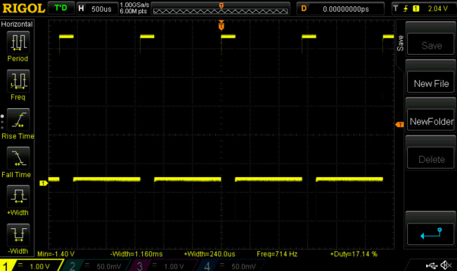
As you can see, the measurements are very similar.
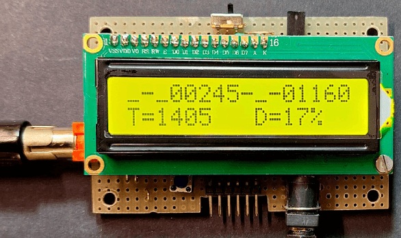
total period T (1,405 μs), and the duty cycle (17%).
PIC16F648 PWMmeter Program Listing
The program is largely similar to the previous one, with the exception of the LCDprint routine. Instructions for calculating and printing the duty cycle have been added. The modified routine is shown in Listing 2.
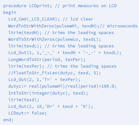
The modified code occupies 2,266 words of flash memory (55%) and 92 bytes of RAM (62%), and compilation was done in 47 ms.
Questions About MCUs, PWM, or the Article?
Do you have technical questions about microcontrollers, PWM, or this article? Please contact the Elektor editorial staff at editor@elektor.com.
The article, "PWM Measurement with a PIC" (230757-01), appears in Elektor May/June 2024.


Discussion (1 comment)