
230V AC dimmer, mains isolated, using P12F629
This is a very simple mains isolated dimmer with a triac output (phase control). It uses timer0 to do the timing.
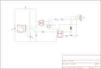
This is a very simple mains isolated dimmer with a triac output (phase control). It uses timer0 to do the timing.
There is no user interface, the value of the triac ignition delay after a zero crossing is defined by setting the reload value of timer0 (Tmr0) in the software directly. This value can e.g. be derived from a user interface or sensor or some algorithm. In the example it is stepped trough a number of values sequentially.
The code is written in mikroPascal from Mikroelektronika, see the code for its details and explanation.
The control part (here a P12F629) is competely isolated from the 230V mains supply:
- the zero crossing detector contains an optocoupler (4N25 or similar),
- the drive of the triac also contains an opto coupler (MOC3025 or similar). Be aware: the latter optocoupler should NOT have a zero cross detection!
The 5V power supply is not drawn in the schematic.
The ignition delay of the triac in series with the load depends on the reload value of Timer0 (Tmr0) in the interrupt routine (zero crossing detected).
The delay (in steps of 64 usecs, the clock of timer0 is 15625 Hz) is given by 256-Tmr0.
The minimum delay (64 us) is achieved by setting the Tmr0 to 255 . This gives maximum power to the load.
The maximum delay needed in this application (10 ms) is achieved by setting Tmr0 to 99 (gives 157 * 64 us = 10.04 ms). This gives no triac ignition at all. Lower values of Tmr0 give the same result.
In the example:
The example uses only these 3 values, see the comments below:
Case Step of
0: Tmr0 := 0; // never ignite triac (delay > 10 ms)
1: Tmr0 := 140; // low value = long delay = late ignition = low power
2: Tmr0 := 175; // average power
3: Tmr0 := 250; // high value = short delay = high power
end;
Want to build a project?
Bring your design to life with the Elektor PCB Service, powered by Eurocircuits. Upload the project files and order professionally manufactured PCBs or assembled boards through a proven European production platform.
Supporting KiCad, Eagle, Gerber, and ODB++ formats, the service is suitable for everything from prototypes and validation builds to series production and volume manufacturing.
Made in Europe. Fast. Reliable. Professional.
Updates from the author