
Bird-drinking-water heating [130256-I]
Many people feed garden birds in the wintertime with seeds, nuts and peanuts. But when the temperature gets below zero degrees celsius, water freezes and the birds don't have drinking water anymore. So it is a good idea to put a small can with drinking water in your garden too and … heat it to keep the water liquid.
Many people feed garden birds in the wintertime with seeds, nuts and peanuts. But when the temperature gets below zero degrees celsius, water freezes and the birds don't have drinking water anymore. So it is a good idea to put a small can with drinking water in your garden too and … heat it to keep the water liquid.
Principle working
The water is heated using a 2N3055 transistor (TO-3 casing). The idea of using a TO-3 transistor was published before in Elektor in november 2007 (see 2N3055-tip.pdf in the datasheets.zip file – only in dutch) A PTC is used to measure the temperature of a small tin (containing the water). The power is supplied by eight rechargeable batteries. A LM339 comparator switches the heating on and off. A second comparator of the LM339 guards the supply voltage of the batteries so they don't get uncharged too much. Two LEDs show the status of the circuit. That's all.
Casing
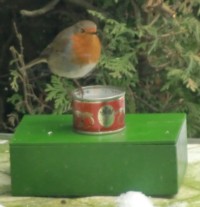
A small tomato paste tin is mounted on a painted wooden cigar box. The tin must be very small for two reasons: first; the less water there is to be heated, the longer the batteries last, but second – and this is very important; birds may not be able to take a bath in the water! Because if they do, later on their feathers freeze and they die. The small tomato paste tin holds more than enough water for a day. Birds use it happily but don't need much drinking water.
The cigar box is sprayed twice with green paint to make it waterresistant. It contains the battery pack and the small electronics board. The tin is mounted on the cover of the cigar box. See BDWH-explosionview.jpg. The PTC is glued on the side of the tin. For further details see the pictures.
Electronics
The LM339 and surrounding components are soldered on a small strips print. See schematics.jpg and printout of PCB.pdf. The LEDs are mounted at the solderside. Potmeter P1 is for adjusting the switching point for the heating to go and off. This can be detected by LED2 (yellow). As said before the PTC is glued on the side of the tin. As a alternative a NTC may be used but then the NTC and R2 have to change places.
If the temperature rises, the resistance of PTC1 rises too, and at a certain moment the output of U1/2 goes low and shuts T1 and T2. R4 limits the current of 'darlington' T1-T2. R4 = 4k7 ohm limits the current through T2 to 100 mA, resulting in approximally 1.2 Watt energy consumption . The lower the value of R4, the more current flows. You may use the following data to calculate the lowest ambient temperature before the water freezes while heated. For a 2N3055: Rth j-c = 1,5 'C/W Rth c-a = 175 'C/W. But this is for air as ambient. The thermal conductivity of air is 0,6 W/(m.k) and for water is 24 W/(m.k). Water conducts 24 / 0,6 = 40 times better than air. So Rth c-a (water) = 175 / 40 = 4,4 'C/w. In this case (consuming 1.2 W) the water starts freezing at temperatures lower than -7 degrees C. Practise results show this to be correct.
If the supply voltage goes lower than 7.5 Volt (D1) then the output of U1/3 goes low and shuts T1. LED1 (red) is the alarmfunction of: heat requested (U1/2) and supply voltage too low (U1/3). This is to protect the rechargeable batteries.
The power supply exists of eight rechargeable Mignon AA cells. The 2700 mA types will supply the heating for about 24 hours. Recharging them with a 500 mA quick charger is done in 4.5 hours. A good idea is to use two sets of eight batteries – one group in use and one group being recharged. Furthermore, it is a good idea to take the whole thing indoors after dark. Birds sleep, so it no use to keep the water liquid during the (cold) nights. Also, before you recharge the batteries, make sure that they have come up to roomtemperature.
PCB
Soldering the components on the print is straight forward. Do not forget to start with the cutting of the strips as marked on the design. Then solder the wire bridges, etc. The LEDS are soldered on the solderside of the print, so they become visible through the cigar box. You could mount the PCB with components to the cigar box cover, but then you will have problems reaching P1 for the adjustment of the switching level..
Want to build a project?
Bring your design to life with the Elektor PCB Service, powered by Eurocircuits. Upload the project files and order professionally manufactured PCBs or assembled boards through a proven European production platform.
Supporting KiCad, Eagle, Gerber, and ODB++ formats, the service is suitable for everything from prototypes and validation builds to series production and volume manufacturing.
Made in Europe. Fast. Reliable. Professional.
Discussion (0 comments)