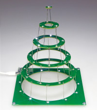
Halfway 2014 we designed a Christmas tree shaped as an upward spiral (http://www.elektor-labs.com/project/130478-xmas-tree-2014.14097.html). The extreme high production costs (0.2 mm PCB) was the reason we didn’t make it available in our store. A variation on the original design is making use of circular PCBs with decreasing diameters placed above each other. This way standard PCB material can be used. If the PCBs would have a fully closed surface the PCB for the entire tree would be enormous (depending on the number of levels) and so again expensive. A cheaper solution is making centric PCB’s that fit in side of each other. Our preferred PCB manufacturer uses a standard 2 mm milling to separate the PCBs, making the outer diameter of an inner PCB 4 mm smaller than the inner diameter of the PCB surrounding it. The PCB design has to be cleaned up and the connections, these also act as spacers, need to be spread more evenly.
Instead of a circuit with standard logic we now use a microcontroller to drive a matrix of 36 LEDs. The LEDs are placed clockwise from bottom to top (LED36). The same type of microcontroller as used in an Arduino Uno is also used here. A SMD version of the ATmega328 is used to keep it more unnoticeable (we want to see the LEDs, not their driving circuit). The PCB has room for an ISP header. If the PCB is finished with a blank controller the firmware can be programmed afterwards. But this also gives the possibility to change the patterns to one’s own view by modifying the firmware later on.
This is just a first idea. Maybe an extra header with jumpers is necessary or micro switches instead, to set different patterns. Or is a random blinking of the LEDs sufficient? At this point software has not been developed yet.
Our first prototype (added 29-9-2015)
The PCB is panelized, meaning 5 inner circles can be broken of the base PCB. If one plans to solder the parts by hand this can be done before the PCB sections are separated. If one plans to use a reflow oven it may be better to mount all parts on the complete PCB and separate the sections afterwards. We placed each next level a little over 3 cm higher using 0.7 mm tinplated wire, but feel free to use green insulated wire or any other color. When soldering the 35 wires (cut them to 4 cm before soldering) temporarily place 3 spacers of equal length to keep the layers exactly parallel. ‘Dressing up’ the tree is something you have to decide for yourself. Add a few small green pine branches or paper. Hang a ball in the middle or maybe add several small ones. Most of my colleges were in favor of a cone shape, so that is what you see in the pictures. Now it’s higher than wide and resembles the shape of a tree somewhat. Another idea is to increase the distance a bit with each next level, creating an ‘exponential’ shape. But that is also something everyone must decide for themselves.
The software (written by Clemens Valens, see separate contribution) randomly lights up leds and a random layer is fully lit (every 15 seconds) and leds on it are turned off one by one (also on a random moment). The trimmer setting changes the speed with which this occurs. 2 seconds minimal with a 5 seconds random factor.
Leds also have different brightness levels.
Bill of materials
Resistor
R1,R2,R3,R4,R5,R6 = 47 Ω, thick film, 5%, 0.1W, SMD 0805
R7 = 10 kΩ, 5%, 0.1W, SMD 0805
P1 = 5 kΩ, 20 %, trimmer, 4.5 mm, 250 mW, SMD
Capacitor
C1,C2 = 22 pF, 50 V, C0G/NP0, SMD 0805
C3,C4 = 100 nF, 50 V, X7R, SMD 0805
C5 = 10 µF, 6.3 V, X5R, SMD 0805
Semiconductor
LED1-LED36 = White led, OVS-0801, SMD 0805
IC1 = ATmega328P-AU, SMD TQFP-32
Other
K1 = Micro USB type B, receptacle, bottom, SMD
K2 = Pin header, 2 rows, 2x3, vertical, through hole, pitch 2.54 mm
X1 = Crystal 16 MHz, 18 pF, SMD 5x3.2 mm
1.5 m wire for 35 connections between levels, diam. 0.7 mm
Misc.
PCB 150453-1 v1.1

Discussion (1 comment)