
DIY Bluetooth Speaker
Advanced Audio Distribution Profile(A2DP) Bluetooth Speaker.
Introduction
Since one year, I am working on ESP32 development board to make a DIY bluetooth speaker to listen my favorite music. After spending a lot of time finally I found a repository on GitHub about ESP32-A2DP by Schatzmann. He has created a library for transmitting and receiving audio over bluetooth using A2DP bluetooth protocol. After reading the given information, I downloaded the ESP32-A2DP library and installed it in my arduino IDE.
Advance Audio Distribution Profile (A2DP)
The Advanced Audio Distribution Profile (A2DP) defines the protocols and procedures that realize distribution of audio content of high quality in mono, stereo, or multi-channel modes. The term “advanced audio”, therefore, should be distinguished from “Bluetooth audio”, which indicates distribution of narrow band voice on SCO channels.[
A typical usage case is the streaming of music content from a stereo music player to headphones or speakers. The audio data is compressed in a proper format for efficient use of the limited bandwidth.
A2DP focuses on audio streaming, while the Video Distribution Profile (VDP) specifies video streaming. Support of both profiles enables the distribution of video content accompanied with high-quality audio. The usage case of video and audio streaming is described in VDP.
Note also that the A2DP does not include remote control functions. Devices may support remote control features by implementing both A2DP and the control profile as depicted, for example, in the usage scenario of Audio/Video Remote Control Profile (AVRCP) .
The following roles are defined for devices that implement this profile:
A2DP Source – A device is the source when it acts as a source of a digital audio stream that is delivered to the SINK of the piconet.
A2DP Sink – A device is the sink when it acts as a sink of a digital audio stream delivered from the SOURCE on the same piconet.
Profile Dependency
In Figure 1.1, the structure and the dependencies of the profiles are depicted. A profile is dependent upon another profile if it re-uses parts of that profile, by implicitly or explicitly referencing it. Dependency is illustrated in the figure. A profile has dependencies on the profile(s) in which it is contained – directly and indirectly.
As indicated in Figure 1.1, the A2DP is dependent upon the Generic Access Profile (GAP), as well as the Generic Audio/Video Distribution Profile (GAVDP) , which defines procedures required to set up an audio/video streaming. The A2DP defines parameters and procedures that are specific for audio streaming. The terminology, user interface and procedures as defined in the GAP and GAVDP are applicable to this profile, unless explicitly stated otherwise.
Audio/video Remote Control Profile (AVRC)
AVRCP is designed to provide a standard interface to control TVs, Hi-Fi equipment, or others to allow a single remote controller (or other device) to control all the A/V equipment to which a user has access. It may be used in concert with A2DP or VDP.
Basically your action manipulates the control. You can adjust menu functions that are already commonly used, such as adjusting the brightness of your TV or hue, or a VCR timer, as well as audio functions like sound adjustments, play, pause, skip, etc. The AVRCP defines two roles, that of a controller and target device.
Controller – The controller is typically considered the remote control device.
Target – The target device is the one whose characteristics are being altered.
In a “Walkman” type media player scenario, the control device may be a headset that allows tracks to be skipped and the target device would be the actual medial player.
In AVRCP, the controller translates the detected user action to the A/V control signal, and then transmits it to a remote Bluetooth enabled device. The functions available in a conventional infrared remote controller can be realized in this profile. AVRCP Browsing enables browsing media content on a media library –aware player.
I2S
General Description
The Integrated Inter-IC Sound Bus (I2S) is a serial bus interface standard used for connecting digital audio devices together. The specification is from Philips Semiconductor (I2S bus specification; February 1986, revised June 5, 1996).
It is a serial bus interface, designed by Philip Semiconductor in February 1986 for digital audio interface between the devices.
What is I2S Protocol?
The protocol which is used to transmit digital audio data from one device to another device is known as I2S or Inter-IC Sound protocol. This protocol transmits PCM (pulse-code modulated) audio data from one IC to another within an electronic device. I2S plays a key role in transmitting audio files which are pre-recorded from an MCU to a DAC or amplifier. This protocol can also be utilized to digitize audio using a microphone. There is no compression within I2S protocols, so you cannot play OGG or MP3 or other audio formats that condense the audio, however, you can play WAV files.
Features
The I2S protocol features include the following.
The I2S communication protocol is a 3 Wire protocol that simply handles audio data through a 3-line serial bus which includes SCK (Continuous Serial Clock), WS (Word Select) & SD (Serial Data).
3-Wire Connection of I2S:
SCK
The SCK or Serial Clock is the first line of the I2S protocol which is also known as BCLK or bit clock line which is used to obtain the data on a similar cycle. The serial clock frequency is simply defined by using the formula like Frequency = Sample Rate x Bits for each channel x no. of channels.
WS
In the I2S communication protocol, the WS or word select is the line which is also known as FS (Frame Select) wire that separates the right or left channel. If WS = 0 then left channel or channel-1 is used.
If WS = 1 then the right channel or channel-2 is used.
SD
The Serial Data or SD is the last wire where the payload is transmitted within 2 complements. So, it is very significant that the MSB is first transferred, because both the transmitter & receiver may include different word lengths. Thus, the transmitter or the receiver has to recognize how many bits are transmitted.
I2S Timing Diagram
For a better understanding of the I2S & its functionality, we have the I2S communication protocol timing diagram shown below. The timing diagram of the I2S protocol is shown below which includes three wires SCK, WS & SD.
I2S Timing Diagram has given in image Fig1.2
MAX98357A I2S Amplifier
General Description
The MAX98357A/MAX98357B is an easy-to-use, low-cost, digital pulse-code modulation (PCM) input Class D amplifier that provides industry-leading Class AB audio performance with Class D efficiency. The digital audio interface automatically recognizes up to 35 different PCM and TDM clocking schemes which eliminates the need for I2C programming. Operation is further simplified by eliminating the need for an external MCLK signal that is typically used for PCM communication. Simply supply power, LRCLK, BCLK, and digital audio to generate audio! Furthermore, a novel pinout allows customers to use the cost-effective WLP package with no need for expensive vias (refer to Application Note 6643: Optimize Cost, Size, and Performance with MAX98357 WLP for more information).
Features
List of Electronic Components
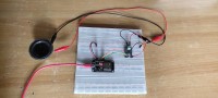
Before soldering the components on a printed circuit board(PCB) make prototype circuit on a breadboard and then test it by uploading the program on ESP32. For making wiring connections I have provided the schematic diagram in pdf format. You can download it. If everything works well only then you can remove all your parts from the breadboard and then start soldering them on a PCB one by one.
If the prototype circuit is not working, please recheck all the wiring connections and polarity of power supply wires. Before using jumper wires, first check all the jumper wires with a multimeter. For testing the wires set the multimeter in continuity mode.
Programming
You can download the code by the following links given below;
Download the ESP32 A2DP Library
https://github.com/pschatzmann/ESP32-A2DP
Download the main program file
https://github.com/ramjipatel041/ESP32-Bluetooth-Speaker.
Since one year, I am working on ESP32 development board to make a DIY bluetooth speaker to listen my favorite music. After spending a lot of time finally I found a repository on GitHub about ESP32-A2DP by Schatzmann. He has created a library for transmitting and receiving audio over bluetooth using A2DP bluetooth protocol. After reading the given information, I downloaded the ESP32-A2DP library and installed it in my arduino IDE.
Advance Audio Distribution Profile (A2DP)
The Advanced Audio Distribution Profile (A2DP) defines the protocols and procedures that realize distribution of audio content of high quality in mono, stereo, or multi-channel modes. The term “advanced audio”, therefore, should be distinguished from “Bluetooth audio”, which indicates distribution of narrow band voice on SCO channels.[
A typical usage case is the streaming of music content from a stereo music player to headphones or speakers. The audio data is compressed in a proper format for efficient use of the limited bandwidth.
A2DP focuses on audio streaming, while the Video Distribution Profile (VDP) specifies video streaming. Support of both profiles enables the distribution of video content accompanied with high-quality audio. The usage case of video and audio streaming is described in VDP.
Note also that the A2DP does not include remote control functions. Devices may support remote control features by implementing both A2DP and the control profile as depicted, for example, in the usage scenario of Audio/Video Remote Control Profile (AVRCP) .
The following roles are defined for devices that implement this profile:
A2DP Source – A device is the source when it acts as a source of a digital audio stream that is delivered to the SINK of the piconet.
A2DP Sink – A device is the sink when it acts as a sink of a digital audio stream delivered from the SOURCE on the same piconet.
Profile Dependency
In Figure 1.1, the structure and the dependencies of the profiles are depicted. A profile is dependent upon another profile if it re-uses parts of that profile, by implicitly or explicitly referencing it. Dependency is illustrated in the figure. A profile has dependencies on the profile(s) in which it is contained – directly and indirectly.
As indicated in Figure 1.1, the A2DP is dependent upon the Generic Access Profile (GAP), as well as the Generic Audio/Video Distribution Profile (GAVDP) , which defines procedures required to set up an audio/video streaming. The A2DP defines parameters and procedures that are specific for audio streaming. The terminology, user interface and procedures as defined in the GAP and GAVDP are applicable to this profile, unless explicitly stated otherwise.
Audio/video Remote Control Profile (AVRC)
AVRCP is designed to provide a standard interface to control TVs, Hi-Fi equipment, or others to allow a single remote controller (or other device) to control all the A/V equipment to which a user has access. It may be used in concert with A2DP or VDP.
Basically your action manipulates the control. You can adjust menu functions that are already commonly used, such as adjusting the brightness of your TV or hue, or a VCR timer, as well as audio functions like sound adjustments, play, pause, skip, etc. The AVRCP defines two roles, that of a controller and target device.
Controller – The controller is typically considered the remote control device.
Target – The target device is the one whose characteristics are being altered.
In a “Walkman” type media player scenario, the control device may be a headset that allows tracks to be skipped and the target device would be the actual medial player.
In AVRCP, the controller translates the detected user action to the A/V control signal, and then transmits it to a remote Bluetooth enabled device. The functions available in a conventional infrared remote controller can be realized in this profile. AVRCP Browsing enables browsing media content on a media library –aware player.
I2S
General Description
The Integrated Inter-IC Sound Bus (I2S) is a serial bus interface standard used for connecting digital audio devices together. The specification is from Philips Semiconductor (I2S bus specification; February 1986, revised June 5, 1996).
It is a serial bus interface, designed by Philip Semiconductor in February 1986 for digital audio interface between the devices.
What is I2S Protocol?
The protocol which is used to transmit digital audio data from one device to another device is known as I2S or Inter-IC Sound protocol. This protocol transmits PCM (pulse-code modulated) audio data from one IC to another within an electronic device. I2S plays a key role in transmitting audio files which are pre-recorded from an MCU to a DAC or amplifier. This protocol can also be utilized to digitize audio using a microphone. There is no compression within I2S protocols, so you cannot play OGG or MP3 or other audio formats that condense the audio, however, you can play WAV files.
Features
The I2S protocol features include the following.
- It has 8 to 32 data bits for each sample.
- Tx & Rx FIFO interrupts.
- It supports DMA.
- 16-bit, 32-bit, 48-bit, or 64-bit word select period.
- Simultaneous bi-directional audio streaming.
- 8-bit, 16-bit, and 24-bit sample width.
- It has different sample rates.
- The data rate is up to 96 kHz through the 64-bit word select period.
- Interleaved stereo FIFOs or Independent right & left channel FIFOs
- Independent enable of Tx & Rx
The I2S communication protocol is a 3 Wire protocol that simply handles audio data through a 3-line serial bus which includes SCK (Continuous Serial Clock), WS (Word Select) & SD (Serial Data).
3-Wire Connection of I2S:
SCK
The SCK or Serial Clock is the first line of the I2S protocol which is also known as BCLK or bit clock line which is used to obtain the data on a similar cycle. The serial clock frequency is simply defined by using the formula like Frequency = Sample Rate x Bits for each channel x no. of channels.
WS
In the I2S communication protocol, the WS or word select is the line which is also known as FS (Frame Select) wire that separates the right or left channel. If WS = 0 then left channel or channel-1 is used.
If WS = 1 then the right channel or channel-2 is used.
SD
The Serial Data or SD is the last wire where the payload is transmitted within 2 complements. So, it is very significant that the MSB is first transferred, because both the transmitter & receiver may include different word lengths. Thus, the transmitter or the receiver has to recognize how many bits are transmitted.
I2S Timing Diagram
For a better understanding of the I2S & its functionality, we have the I2S communication protocol timing diagram shown below. The timing diagram of the I2S protocol is shown below which includes three wires SCK, WS & SD.
I2S Timing Diagram has given in image Fig1.2
MAX98357A I2S Amplifier
General Description
The MAX98357A/MAX98357B is an easy-to-use, low-cost, digital pulse-code modulation (PCM) input Class D amplifier that provides industry-leading Class AB audio performance with Class D efficiency. The digital audio interface automatically recognizes up to 35 different PCM and TDM clocking schemes which eliminates the need for I2C programming. Operation is further simplified by eliminating the need for an external MCLK signal that is typically used for PCM communication. Simply supply power, LRCLK, BCLK, and digital audio to generate audio! Furthermore, a novel pinout allows customers to use the cost-effective WLP package with no need for expensive vias (refer to Application Note 6643: Optimize Cost, Size, and Performance with MAX98357 WLP for more information).
Features
- Single-Supply Operation (2.5V to 5.5V)
- 3.2W Output Power into 4Ω at 5V
- 2.4mA Quiescent Current
- 92% Efficiency (RL = 8Ω, POUT = 1W)
- Sample Rates of 8kHz to 96kHz
- 77dB PSRR at 1kHz
- Robust Short-Circuit and Thermal Protection
- Available in Space-Saving Packages: 1.345mm x 1.435mm WLP (0.4mm Pitch) and 3mm x 3mm TQFN
List of Electronic Components
- ESP-Wroom-32
- MAX98357A I2S Amplifier
- 4 Ohm/3W Loudspeaker
- MT3608 boost converter module
- 3.7V 1000mah Li-po battery
- TP4056 charging and protection circuit
- Switch
- PCB
- PCB terminal
- Micro-B USB Cable
- Soldering Iron(60W)
- Soldering Flux
- Soldering wire
- Screw Driver
- Saw
- File
Before soldering the components on a printed circuit board(PCB) make prototype circuit on a breadboard and then test it by uploading the program on ESP32. For making wiring connections I have provided the schematic diagram in pdf format. You can download it. If everything works well only then you can remove all your parts from the breadboard and then start soldering them on a PCB one by one.
If the prototype circuit is not working, please recheck all the wiring connections and polarity of power supply wires. Before using jumper wires, first check all the jumper wires with a multimeter. For testing the wires set the multimeter in continuity mode.
Programming
You can download the code by the following links given below;
Download the ESP32 A2DP Library
https://github.com/pschatzmann/ESP32-A2DP
Download the main program file
https://github.com/ramjipatel041/ESP32-Bluetooth-Speaker.
Want to build a project?
Bring your design to life with the Elektor PCB Service, powered by Eurocircuits. Upload the project files and order professionally manufactured PCBs or assembled boards through a proven European production platform.
Supporting KiCad, Eagle, Gerber, and ODB++ formats, the service is suitable for everything from prototypes and validation builds to series production and volume manufacturing.
Made in Europe. Fast. Reliable. Professional.
Discussion (0 comments)