
GPS Distancing - a great aid for the pipe line patrollers
GPS Distancing is the project which took birth out of compulsion. For taking long readings of our pipe lines this device is just unparallel !
GPS Distancing
“GPS Distancing” The term may sound wrong but utility wise that's of great use to them. Who ? My patrollers who scores the 300 km pipe line corridors up and down ,24*7 for leakages, maintenance and measurements of works in our vast ash dykes of 2000 acres.
Each zone is looked after by one patroler for the 8 hours shift. They have to take measurement for laying a new route , replacement / shifting of old routes and extension of lines deep inside the dyke with measurements. All these are quite often and each time they have to call the neighboring patroller for holding the one end of the big measuring tape for taking the measurement. Not to mention that many times the tape sags on the marshy wet mud land making it dirty & soiled. Also to note that every time after taking readings they have to wind up the tape inside the reel.
The demand of this 'GPS Distancing' started from here.
Arduino on internal 8 MHz clock: To make the circuitry simple and less power consuming everything including the 16 MHz resonator, small pico capacitors are removed and the Arduino is programmed on the bare minimum ATMEGA328P -PU on internal 8MHz clock.
Operations: Since the the pipe lines are all under the open sky the connection with the GPS satellites which are on the LEO (Low Earth Orbit) are almost instant. The cold-start of the GPS device starts up in less than 20 seconds even ! You will come to know about this when the PPS (Pulse Per Second) green light flashes continuously on the inexpensive GPS receiver.
Immediately the Latitude and the Longitude readings along with the date and time will flash on the small 4*16 LCD panel. Press the push button provided for reading and the initial reading will be marked. Move to the desired location for taking distance reading and then press this button again. The distance will flash on the 3 rd line of the LCD and at the same time the readings (serial, date, time,lat, lon, dist_inst, dist_total will be dumped in a text file which will be stored on a small SDcard (8GB, 16GB etc.) attached with the device. For distance measurement we have used the popular 'Haversine' formula. The Lat & Lon readings are taken upto 6 th decimal precision and then used up for calculations. The double precision variable is used for the same.
The chances of error may be to the tune of 2.5 meter to 10 meter but believe me under the open sky where the location of GPS satellites are very easy, the error is absolutely minimum. I never got even a 5 meter error to our 2000 acre Vindhyanagar ash dyke areas.
On a cloudy day the sighting of the GPS may take little longer for the GPS receiver therefore, before pressing the push button wait a while for the Lat. And the Lon. reading gets stabilized.
Schematic: Initially I aimed to put a small I2C TFT instead of this cumbersome 4*16 LCD panel but the TFT requires many header files – adafruit GFX, SSD3106, wire.h which when combines with SPI, TinyGPS & SDFat header file, it becomes too much for the poor ATMEGA328 to take up. In Arduino MEGA this can be done comfortably but the form factor & power consumption would have been more.
Therefore, I stripped all those TFT related files and used only the following minimum
header files with a 4*16 LCD panel.
liquidcrystal.h for LCD pannel
TinyGPS.h for GPS readings
SPI.h for connecting SDCardSDFat.h for SD card
The Arduino is ATMEGA328P – PU , the low power MCU.
To reduce the power consumption further we have connected it on 3.3 volt and clocked it on the internal 8MHz resonator. The circuitry becomes very simple and easy. On a small li-ion battery (1.9 Whour, 250 mA) it works for near about 3 hours.
However, the LCD has a profound drawback, that it runs only on 5 volt supply only. For that only I had to arrange a 5 Volt supply using a 7805 IC otherwise the Arduino works fine upto 1.8 volts even ! However, the GPS module requires 3.3 volt supply and it takes some 40 mA current too as it has 2 LEDs on it's top and another green LED for PPS blink. In total the device takes 85 to 95 mA current on 7.4 volt. We tried with power down mode but it does not work on internal 8 MHz mode. Perhaps a 3.3 volt LCD panel would make the device more simple !
Figure-1:
Device from top
Figure-2:
Device from bottom (see the two push buttons)
Programming: For programming on an ATMEGA328 with a 16MHz resonator attached externally is very easy – it's nothing but an Arduino UNO which will also work for this project but to get it programmed on 8MHz internal clock is rather challenging. For that you have to find out an un- programmed ATMEGA328 which has never been programmed with 16MHz external resonator. Because once it is programmed with an external clock it will never go back to 8MHz internal clock mode. See 'Arduino on board' for programming it with 8MHz internal clock.
Advantage of 8MHz internal clock: It's easy to make connections on a piece of vero board besides it's power consumption is not even 10 mA on 3.3 volt supply. It lasts very loooooong !
Operations: Wait till the PPS LED on the GPS start blinking. Soon you will find the Lattitude and Longitude is flashing on the 4*16 LCD. Get the readings stabilized on the LCD. Press the reading button and the instantaneous distance will be shown with total distance on the third line of the LCD panel. The same reading along with serial number, date & time will go to the data file in the SDCard attached. Then move to your next spot to measure the distance and then press the reading button to get the distance. Finally when you are over then press the other button which will close the file and halt the system. Reset Arduino to restart the system.
Figure-3: (The beginning → before pressing the reading button)
Figure-4: First reading ; Press the reading button , keep it pressed.
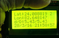
Figure-5:
Figure-6: The d = Instantaneous distance; A to B to C to D to E etc. While the D = A to B, A to C , A to D etc.
Logging:
Every time you start the Device , it will create a new log file with name data0.csv, data01,csv, data02,csv etc. The contents of the file looks like ...
Sl Date Time Lattitude Longitude Dist. Dist0
0 20/3/16 23:1:18 24.088750 82.648200 0.0000 0.0000
1 20/3/16 23:1:21 24.088750 82.648200 0.0000 0.0000
2 20/3/16 23:1:24 24.088750 82.648200 0.0000 0.0000
3 20/3/16 23:1:29 24.088750 82.648200 0.0000 0.0000
Software:
[As attached the arduino sketch file]
Uploading: For this refer to https://www.elektormagazine.com/labs/arduino-on-board-1, here . However, you can also use simple UNO for uploading the sketch which will work but with little more power consumption.
Schematic of the device:
Bye, bye
S. Bera
Vindhyanagar
“GPS Distancing” The term may sound wrong but utility wise that's of great use to them. Who ? My patrollers who scores the 300 km pipe line corridors up and down ,24*7 for leakages, maintenance and measurements of works in our vast ash dykes of 2000 acres.
Each zone is looked after by one patroler for the 8 hours shift. They have to take measurement for laying a new route , replacement / shifting of old routes and extension of lines deep inside the dyke with measurements. All these are quite often and each time they have to call the neighboring patroller for holding the one end of the big measuring tape for taking the measurement. Not to mention that many times the tape sags on the marshy wet mud land making it dirty & soiled. Also to note that every time after taking readings they have to wind up the tape inside the reel.
The demand of this 'GPS Distancing' started from here.
Arduino on internal 8 MHz clock: To make the circuitry simple and less power consuming everything including the 16 MHz resonator, small pico capacitors are removed and the Arduino is programmed on the bare minimum ATMEGA328P -PU on internal 8MHz clock.
Operations: Since the the pipe lines are all under the open sky the connection with the GPS satellites which are on the LEO (Low Earth Orbit) are almost instant. The cold-start of the GPS device starts up in less than 20 seconds even ! You will come to know about this when the PPS (Pulse Per Second) green light flashes continuously on the inexpensive GPS receiver.
Immediately the Latitude and the Longitude readings along with the date and time will flash on the small 4*16 LCD panel. Press the push button provided for reading and the initial reading will be marked. Move to the desired location for taking distance reading and then press this button again. The distance will flash on the 3 rd line of the LCD and at the same time the readings (serial, date, time,lat, lon, dist_inst, dist_total will be dumped in a text file which will be stored on a small SDcard (8GB, 16GB etc.) attached with the device. For distance measurement we have used the popular 'Haversine' formula. The Lat & Lon readings are taken upto 6 th decimal precision and then used up for calculations. The double precision variable is used for the same.
The chances of error may be to the tune of 2.5 meter to 10 meter but believe me under the open sky where the location of GPS satellites are very easy, the error is absolutely minimum. I never got even a 5 meter error to our 2000 acre Vindhyanagar ash dyke areas.
On a cloudy day the sighting of the GPS may take little longer for the GPS receiver therefore, before pressing the push button wait a while for the Lat. And the Lon. reading gets stabilized.
Schematic: Initially I aimed to put a small I2C TFT instead of this cumbersome 4*16 LCD panel but the TFT requires many header files – adafruit GFX, SSD3106, wire.h which when combines with SPI, TinyGPS & SDFat header file, it becomes too much for the poor ATMEGA328 to take up. In Arduino MEGA this can be done comfortably but the form factor & power consumption would have been more.
Therefore, I stripped all those TFT related files and used only the following minimum
header files with a 4*16 LCD panel.
liquidcrystal.h for LCD pannel
TinyGPS.h for GPS readings
SPI.h for connecting SDCardSDFat.h for SD card
The Arduino is ATMEGA328P – PU , the low power MCU.
To reduce the power consumption further we have connected it on 3.3 volt and clocked it on the internal 8MHz resonator. The circuitry becomes very simple and easy. On a small li-ion battery (1.9 Whour, 250 mA) it works for near about 3 hours.
However, the LCD has a profound drawback, that it runs only on 5 volt supply only. For that only I had to arrange a 5 Volt supply using a 7805 IC otherwise the Arduino works fine upto 1.8 volts even ! However, the GPS module requires 3.3 volt supply and it takes some 40 mA current too as it has 2 LEDs on it's top and another green LED for PPS blink. In total the device takes 85 to 95 mA current on 7.4 volt. We tried with power down mode but it does not work on internal 8 MHz mode. Perhaps a 3.3 volt LCD panel would make the device more simple !
Figure-1:
Device from top
Figure-2:
Device from bottom (see the two push buttons)
Programming: For programming on an ATMEGA328 with a 16MHz resonator attached externally is very easy – it's nothing but an Arduino UNO which will also work for this project but to get it programmed on 8MHz internal clock is rather challenging. For that you have to find out an un- programmed ATMEGA328 which has never been programmed with 16MHz external resonator. Because once it is programmed with an external clock it will never go back to 8MHz internal clock mode. See 'Arduino on board' for programming it with 8MHz internal clock.
Advantage of 8MHz internal clock: It's easy to make connections on a piece of vero board besides it's power consumption is not even 10 mA on 3.3 volt supply. It lasts very loooooong !
Operations: Wait till the PPS LED on the GPS start blinking. Soon you will find the Lattitude and Longitude is flashing on the 4*16 LCD. Get the readings stabilized on the LCD. Press the reading button and the instantaneous distance will be shown with total distance on the third line of the LCD panel. The same reading along with serial number, date & time will go to the data file in the SDCard attached. Then move to your next spot to measure the distance and then press the reading button to get the distance. Finally when you are over then press the other button which will close the file and halt the system. Reset Arduino to restart the system.
Figure-3: (The beginning → before pressing the reading button)
Figure-4: First reading ; Press the reading button , keep it pressed.
Figure-5:
Figure-6: The d = Instantaneous distance; A to B to C to D to E etc. While the D = A to B, A to C , A to D etc.
Logging:
Every time you start the Device , it will create a new log file with name data0.csv, data01,csv, data02,csv etc. The contents of the file looks like ...
Sl Date Time Lattitude Longitude Dist. Dist0
0 20/3/16 23:1:18 24.088750 82.648200 0.0000 0.0000
1 20/3/16 23:1:21 24.088750 82.648200 0.0000 0.0000
2 20/3/16 23:1:24 24.088750 82.648200 0.0000 0.0000
3 20/3/16 23:1:29 24.088750 82.648200 0.0000 0.0000
Software:
[As attached the arduino sketch file]
Uploading: For this refer to https://www.elektormagazine.com/labs/arduino-on-board-1, here . However, you can also use simple UNO for uploading the sketch which will work but with little more power consumption.
Schematic of the device:
Bye, bye
S. Bera
Vindhyanagar
Build This Project
Bring this design to life with the Elektor PCB Service, powered by Eurocircuits. Upload the project files and order professionally manufactured PCBs or assembled boards through a proven European production platform.
Supporting KiCad, Eagle, Gerber, and ODB++ formats, the service is suitable for everything from prototypes and validation builds to series production and volume manufacturing.
Made in Europe. Fast. Reliable. Professional.
Discussion (1 comment)