
Hydro plant telemetry
I never knew such a perinnial problem could be solved so easily when Sh RS was at his wits end following up between the Cell companies & IT dept.
Hydel plant telemetry
Ever since the new mini hydel plant have been handed over to the new sister organization, the whole problem started. Compared to the main business of about 2000 megawatt thermal power generation, this 10 mega watt mini hydro has no significance in the main portfolio except that it’s renewable energy and it has huge & long time importance in the future of power business. So far till now, the earlier management used to monitor the daily generation only once at the end of the day. The energy meter reading whatever it changes, brings the total energy sent out through the grid and it was the only parameter being monitored by the earlier management.
But the new management wanted a live data monitoring atleast for a few parameters like – instant mega watt generation, water head level and tail race level for the 2x5 MW hydro turbine. Accordingly an enquiry was sent through the capable vendors and the quotations came in the tune of INR 12 lacs [Maximum] to INR 10.5 lacs [Minimum] [ $16216 USD to $15540 USD]
The first reaction came from management was that such a huge budget is not available for such a small capacity setup. In power generation the capacity addition comes under CAPEX budget which is actually passed through to the users over a 10 year spread as fixed cost recovery with interest. Management is not ready to augment the fixed cost recovery for this small setup now.
Knowing my works on telemetry, the manager of the hydro plant, one day set up a meeting with me and requested me to find out some way for his requirements. The IT department tried to set up an SMS based GPRS station there but because of the poor reception of cellular GPRS network , the project did not take off. They even tried to change the service providers but all failed to connect a stable internet to deliver the SMS.
The location of the hydro station is way out of the city limit near the G C Panth lake area where the cellular network is available but the GPRS [General Packet Radio System] for internet is not available. Thus this project was born. While the road journey takes about 8.5 kilo meter down to the hinterland of the hydel power station location, the google map says it’s just about 5.9 kilometer aerial distance from our stage-X control room up to the hydel station.
Proof of concept & a pilot testing:
I had conviction that low speed telemetry based on spread spectrum radio between this much distance is highly possible. To have a pilot testing ,next day I sent a supervisor there with the small Arduino based battery operated SS sender on a small hand held antenna. I instructed him to stand on the hydel station roof facing the stage-x control room. While I, standing on the stage-x control room roof switched on the receiver model which is also a simple Arduino based battery operated receiver. And lo, it receives the signal all the way from the hydel station. The radiation used is only 200 mili watt and free allowed band [of 863 ~ 867 Mhz free band in our country]
Main project: Sh RS was exuberant when I broke the news to him that I got the signal over the air. Next day I made another visit to the hydel station to see the signaling panel, wherefrom I have to pick up data from the instrumentation panel, convert it from current to voltage and then insert it into the GPIOs of my microprocessors for measurements and transmission.
[Issue-1]
There are lots of issues which I did not anticipate earlier. The hydel station is situated deep down below the ground level and the roof is almost 120 meters above. That means either I have to run the antenna to 120 meter long or bring the signal upto 120 meter distance! The instrumentation engineer said that he cannot guarantee of signal integrity upto that long. So I have to run an antenna upto 120 meters … never ever did that. So far in all my telemetry projects, have antennas just a few centimeters away from the output!
First I decided to set up a 3.5 DBi antenna on a long 120 meter RJ45 coaxial cable. The instrumentation department provided the best quality coaxial cable which I run from roof top to the control room below ground level. While for antenna I required to run 120 meter cable at the hydel station, I had to use about 70 meter cable to run the antenna from stage-x roof top to stage-x control room.
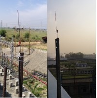
These are my two handmade antennas [3.5 DBi] erected on two sides. The arial distance between these two antennas is approximately 5900 meters. The vision is clear and without any obstruction.
[Issue-2]
Schematic on ESP32:
ESP32 analog pins take upto 3300 milli volt to read as 4095 [0 to 4095]. Therefore to read 20 mA as 3300 milli voltage we have to put a 165 OHM resistor across it to get 20 * 165 = 3300 volt. [I * R = V] But there is no 165 OHM standard resistor available in the market. The instrumentation man told me to put two 330 OHM resistors in parallel to get exactly 165 OHM resistor. So we put 12 , 330 OHM resistors parallel to convert 6 no of inputs into 3300 mV signal. [Later I found that in aliexpress.com the 4 ~ 20 mA to 0 ~3300 / 5000 / 10000 milli volt conversion kit is available for as low as $2 a piece ]
As per the instrumentation man all these inputs are floating inputs, therefore joining one side of all these inputs to ground of the ESP32 will not change / affect the signal. So far so good. Now look at the schematic of the uploader unit. 1 to 6 are the six inputs, each having 2 wires – total 12 wires. One wire is joined together to form the ground. From the remaining 6 wires 165 OHM [2 nos 330 OHM in parallel] resistor is connected. This will give rise to the potential difference of 660 mv to 3300 mv [corresponding to 4 to 20 mA] across each signal wire to the ground. Thus, the six signals ,suitable to the ESP32 is derived. To keep an eye on the time, we have fixed an DS3231 RTC to the I2C bus of the ESP32. The sender module will transmit all data once in 4 seconds along with a date-time stamp.
Prototype uploader:
Most of the resistors are crammed below the OLED and the transceiver. Now look at the schematic behind the prototype.
Schematic of Receiver:
Prototype of the receiver:
While with the stage-x end external antenna works very well, the small omnidirectional antenna also works good when it is checked at 3rd floor or above at the control room building. The reason being the line of sight is devoid of any structure or building.
The instrumentation man is going to give me more signal in the next couple of months. Then I will replace the processor by another ESP32 and the display too will be replaced by another
Bill of materials:
Uploader / Sender Unit all prices are in USD
Handheld Receiver Unit all prices are in USD
For the receiver unit, the external antenna will be used when we are going to install the project inside the control room. While till that time the signal is pretty available near the windows and to some strategic positions inside the control room.
Construction: Is done on general purpose PCBs.
Final outcome: Once we get the remaining 4 signals we will shift the entire output on to processing [processing.org] output with periodic data dumping in database. In that case the use of Uno on the receiver unit will be redundant as the UART transceiver will be connected directly to the USB vide a USB to serial bridge software on a laptop / desktop computer and then the processing will get data directly from the serial port.
However, till going to publish this project Sh RS is proposing 34 more signals to process & upload. For so many signals I have to either use port expanders like MCP23017 or processor like arduino MEGA processor.
Software & Header files are all included:
Bye, bye
S. Bera
Vindhyanagar
Ever since the new mini hydel plant have been handed over to the new sister organization, the whole problem started. Compared to the main business of about 2000 megawatt thermal power generation, this 10 mega watt mini hydro has no significance in the main portfolio except that it’s renewable energy and it has huge & long time importance in the future of power business. So far till now, the earlier management used to monitor the daily generation only once at the end of the day. The energy meter reading whatever it changes, brings the total energy sent out through the grid and it was the only parameter being monitored by the earlier management.
But the new management wanted a live data monitoring atleast for a few parameters like – instant mega watt generation, water head level and tail race level for the 2x5 MW hydro turbine. Accordingly an enquiry was sent through the capable vendors and the quotations came in the tune of INR 12 lacs [Maximum] to INR 10.5 lacs [Minimum] [ $16216 USD to $15540 USD]
The first reaction came from management was that such a huge budget is not available for such a small capacity setup. In power generation the capacity addition comes under CAPEX budget which is actually passed through to the users over a 10 year spread as fixed cost recovery with interest. Management is not ready to augment the fixed cost recovery for this small setup now.
Knowing my works on telemetry, the manager of the hydro plant, one day set up a meeting with me and requested me to find out some way for his requirements. The IT department tried to set up an SMS based GPRS station there but because of the poor reception of cellular GPRS network , the project did not take off. They even tried to change the service providers but all failed to connect a stable internet to deliver the SMS.
The location of the hydro station is way out of the city limit near the G C Panth lake area where the cellular network is available but the GPRS [General Packet Radio System] for internet is not available. Thus this project was born. While the road journey takes about 8.5 kilo meter down to the hinterland of the hydel power station location, the google map says it’s just about 5.9 kilometer aerial distance from our stage-X control room up to the hydel station.
Proof of concept & a pilot testing:
I had conviction that low speed telemetry based on spread spectrum radio between this much distance is highly possible. To have a pilot testing ,next day I sent a supervisor there with the small Arduino based battery operated SS sender on a small hand held antenna. I instructed him to stand on the hydel station roof facing the stage-x control room. While I, standing on the stage-x control room roof switched on the receiver model which is also a simple Arduino based battery operated receiver. And lo, it receives the signal all the way from the hydel station. The radiation used is only 200 mili watt and free allowed band [of 863 ~ 867 Mhz free band in our country]
Main project: Sh RS was exuberant when I broke the news to him that I got the signal over the air. Next day I made another visit to the hydel station to see the signaling panel, wherefrom I have to pick up data from the instrumentation panel, convert it from current to voltage and then insert it into the GPIOs of my microprocessors for measurements and transmission.
[Issue-1]
There are lots of issues which I did not anticipate earlier. The hydel station is situated deep down below the ground level and the roof is almost 120 meters above. That means either I have to run the antenna to 120 meter long or bring the signal upto 120 meter distance! The instrumentation engineer said that he cannot guarantee of signal integrity upto that long. So I have to run an antenna upto 120 meters … never ever did that. So far in all my telemetry projects, have antennas just a few centimeters away from the output!
First I decided to set up a 3.5 DBi antenna on a long 120 meter RJ45 coaxial cable. The instrumentation department provided the best quality coaxial cable which I run from roof top to the control room below ground level. While for antenna I required to run 120 meter cable at the hydel station, I had to use about 70 meter cable to run the antenna from stage-x roof top to stage-x control room.
These are my two handmade antennas [3.5 DBi] erected on two sides. The arial distance between these two antennas is approximately 5900 meters. The vision is clear and without any obstruction.
[Issue-2]
Schematic on ESP32:
ESP32 analog pins take upto 3300 milli volt to read as 4095 [0 to 4095]. Therefore to read 20 mA as 3300 milli voltage we have to put a 165 OHM resistor across it to get 20 * 165 = 3300 volt. [I * R = V] But there is no 165 OHM standard resistor available in the market. The instrumentation man told me to put two 330 OHM resistors in parallel to get exactly 165 OHM resistor. So we put 12 , 330 OHM resistors parallel to convert 6 no of inputs into 3300 mV signal. [Later I found that in aliexpress.com the 4 ~ 20 mA to 0 ~3300 / 5000 / 10000 milli volt conversion kit is available for as low as $2 a piece ]
As per the instrumentation man all these inputs are floating inputs, therefore joining one side of all these inputs to ground of the ESP32 will not change / affect the signal. So far so good. Now look at the schematic of the uploader unit. 1 to 6 are the six inputs, each having 2 wires – total 12 wires. One wire is joined together to form the ground. From the remaining 6 wires 165 OHM [2 nos 330 OHM in parallel] resistor is connected. This will give rise to the potential difference of 660 mv to 3300 mv [corresponding to 4 to 20 mA] across each signal wire to the ground. Thus, the six signals ,suitable to the ESP32 is derived. To keep an eye on the time, we have fixed an DS3231 RTC to the I2C bus of the ESP32. The sender module will transmit all data once in 4 seconds along with a date-time stamp.
Prototype uploader:
Most of the resistors are crammed below the OLED and the transceiver. Now look at the schematic behind the prototype.
Schematic of Receiver:
Prototype of the receiver:
While with the stage-x end external antenna works very well, the small omnidirectional antenna also works good when it is checked at 3rd floor or above at the control room building. The reason being the line of sight is devoid of any structure or building.
The instrumentation man is going to give me more signal in the next couple of months. Then I will replace the processor by another ESP32 and the display too will be replaced by another
Bill of materials:
Uploader / Sender Unit all prices are in USD
- ESP32 - $4
- SSD1306 - $3
- RTC DS3231 - $3
- UART SS Transceiver from ebyte [868 MHz*] - $6.6
- Coaxial – RJ45 cable 120 meter - $100
- Resistors - 6 x 5.6K, 12 x 330 OHM, 1 no 1K
- PCB, SMPS – 5V, 12 SWG cable for 3.5 DBi antenna, wires extra from internal resources.
Handheld Receiver Unit all prices are in USD
- Arduino UNO - $3.5
- UART SS Transceiver from ebyte [868 MHz*] - $6.6
- ILI9488 TFT 3.5 Inch display - $8
- 3.5 DBi 868 MHz antenna - $3
- PCB, SMPS – 5V, wires extra from internal resources.
- 70 Meter Coaxial RJ-45 cable for external antenna from internal resources [optional]
For the receiver unit, the external antenna will be used when we are going to install the project inside the control room. While till that time the signal is pretty available near the windows and to some strategic positions inside the control room.
Construction: Is done on general purpose PCBs.
Final outcome: Once we get the remaining 4 signals we will shift the entire output on to processing [processing.org] output with periodic data dumping in database. In that case the use of Uno on the receiver unit will be redundant as the UART transceiver will be connected directly to the USB vide a USB to serial bridge software on a laptop / desktop computer and then the processing will get data directly from the serial port.
However, till going to publish this project Sh RS is proposing 34 more signals to process & upload. For so many signals I have to either use port expanders like MCP23017 or processor like arduino MEGA processor.
Software & Header files are all included:
Bye, bye
S. Bera
Vindhyanagar
Want to build a project?
Bring your design to life with the Elektor PCB Service, powered by Eurocircuits. Upload the project files and order professionally manufactured PCBs or assembled boards through a proven European production platform.
Supporting KiCad, Eagle, Gerber, and ODB++ formats, the service is suitable for everything from prototypes and validation builds to series production and volume manufacturing.
Made in Europe. Fast. Reliable. Professional.
Discussion (0 comments)