
Li-Ion charger with MIC79050 (150580-I)
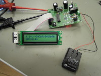
This project uses a Micrel (Microchip) MIC79050 IC for charging 3.7V Li-Ion cells. It also monitors the battery's voltage, current and energy.
This design is based on the Micrel (=Microchip) MIC79050 Lithium Ion battery charger IC. An INA219 monitors the battery voltage and charge/discharge current flowing through shunt resistor R6. T1 switches the charger on and off. D1 and R2 are used for formatting deeply discharged batteries, T2 and R9 are used for discharging. Relay Re1 disconnects the battery in case of power failure.
Features:
Battery formatting: when the battery voltage is lower than 2.7V, it will be charged with a maximum current of 20mA until 2.71V is reached. Then normal charging will start.
Charging: The MIC79050 will limit the charging current to approx. 500mA. When the current drops below 80mA, the battery is considered charged and the charging process is stopped. The total energy is measured and displayed on the LCD (in mAh).
Time-out function: After 30 hours of charging or formatting the process is terminated.
Discharging: The battery is discharged with a 10 Ohm resistor until its voltage drops to 3.0V. The total energy (in mAh) is measured and displayed on the LCD.
The LCD will display the following information:
Total (dis-)charging time
Current voltage and (dis)charging current
Total energy in mAh
Remaining charging time until time-out (hours)
A bi-colour LED gives the following indications:
Orange (both red and green on): battery formatting
Red: charging current > 200mA
Green: charging current between 80mA and 200mA
Blinking red: discharging
Off: no (dis)charging
BOM
Resistor
R1 = 270 Ω, carbon film, 5%, 0.25W, 250V
R2,R8 = 1 kΩ, carbon film, 5%, 0.25W, 250V
R3 = 3.3 kΩ, carbon film, 5%, 0.25W, 250V
R4,R5 = 4.7 kΩ, carbon film, 5%, 0.25W, 250V
R6 = 100mOhm, 5%, 1W
R7 = 1.5 kΩ, carbon film, 5%, 0.25W, 250V
R9 = 10 Ω, carbon film, 5%, 2W, 350V
P1 = 10 kΩ, trimmer, flat
Capacitor
C1,C2,C4 = 100 nF, 50 V, X7R, 5.08 mm pitch
C3 = 100 µF, 50V, 3.5 mm pitch, 8x11 mm
C5 = 220 µF, 25V, 5 mm pitch, 10x16 mm
C6 = 1000 µF, 25V, 7.5 mm pitch, 16x26 mm
C7 = 33nF, 63V, PET, 5.08 mm pitch
Inductor
L1 = 100uH, 190mOhm, 900mA MCSCH895-101KU
Semiconductor
D1,D2,D3 = 1N4007, 1000 V, 1 A
D4 = 1N5817, 20 V, 1 A, Vf=450 mV @ If=1 A
T1 = FQP27P06X, -60 V, -27 A, 120 W, Vgs=-4 V, Rdson=70 mΩ
T2 = IRF540NPBF, 100 V, 33 A, 130 W, Vgs=4 V, Rdson=44 mΩ
LED1 = bi-colour LED red/green, 3-pin CC, L-3VEGW
LED2 = LED, red, 3 mm
IC1 = PIC16F1829-I/P EPS 150580-41
IC2 = Li-Ion battery charger MIC79050-4.2YS
IC3 = Buck switching regulator LT1076CT-5
IC4 = Current sense amplifier INA219AIDR
Other
LCD1 = 2 x 20 character LCD with backlight
LCD1 = 16-way boxheader
K1 = Pin header, breakable, 1 row, 6-way, vertical
K2,K3 = Terminal block 5.08 mm, 2-way, 630 V
S1,S2 = Switch, tactile, 24 V, 50 mA, 6x6 mm
RE1 = Relay, 5 V, SPST, 5 A
PCB 150580-1 v2.0
16 way flatcable, 15cm + 2 x 16-way flatcable connectors
NOTE: LED1, LED2, S1, S2 mounted on bottom side
Build This Project
Bring this design to life with the Elektor PCB Service, powered by Eurocircuits. Upload the project files and order professionally manufactured PCBs or assembled boards through a proven European production platform.
Supporting KiCad, Eagle, Gerber, and ODB++ formats, the service is suitable for everything from prototypes and validation builds to series production and volume manufacturing.
Made in Europe. Fast. Reliable. Professional.
Discussion (1 comment)