
Maximum Power Point Tracking for Solar Photovoltaic Panel [150411]
MPPT – Maximum Power Point Tracker
MPPT – Maximum Power Point Tracker
Funny most of the solar panel that I see around my place even some are very big from 25KW to 2MW but none are controlled by any MPPT. 25% power is straight away lost for poor operating zone of parameter. For battery chargers in the morning when the battery is drained and is near about 11 volt and it gets first power from the panel, it pulls the solar voltage so much down that you loose considerable amount of power at 11 volt (see chart) . On the other hand at peak noon when the battery is fully charged at about 13.6 volt, it still does not allow the panel to produce maximum power for other loads as at 13.6 volt. It still operates far away from it's MPPT; i.e 17.5 volt. MPPT always adjust the load impedance in such a way that the panel always produce V*I for maximum.
But to be frank building an MPPT is really easy. The micro controller does it all for you. Only you have to build the MPPT algorithm very strong and sound which can very quickly struck on to the right spot of MPPT and then it goes on tracking that spot through out the day.
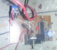
Figure-1 [prototype]
A typical solar Photo Voltaic panel actually acts as a current source. When the current is blocked ,it is converted into voltage & current, thus produces power. But if you draw more and more current , the voltage goes on reducing while on the other side when the current is reduced the voltage goes on increasing. The maximum power is obtained where the product of V*I becomes maximum. In the picture the point is indicated as Maximum Power Point (the knee of the curve). The MPP is obtained by varying the load connected to the circuit. If we add a bigger load the voltage will be reduced and for a smaller load the voltage will be increased. Theoretically
[photo courtesy : Internet ]
the MPPT is at 17.5 Volt at 25 Degree Celsius but in actual case it varies very widely.
The ambient condition plays havoc on the output of a solar PV cell.
Figure-2 [Impact of temperature]
picture courtesy : Internet
If the solar irradiation changes the curve takes a new shape so is the MPP. If the ambient temperature changes the PV curve takes a still newer shape so the MPP also changes. But if we can keep changing the load accordingly we will always be able to get maximum power out of the solar panel.
Figure-3 : MPPT of a 120 watt panel
picture courtesy : Internet
That's a typical 120 watt PV panel. If we connect the panel to a 12 Volt lead acid cell for charging with out MPPT ,the panel will operate from 13.6volt (full charge ) to 11.5 volt (full discharge). At this point the panel will not be able to deliver the shaded amount of power as it is not able to reach that MPT voltage at all which is normally at 17.5 volt - the knee of the curve. The amount of power that we loose is quite havoc – almost 25%.
Here we will develop an Arduino based MPPT which will acts as a valve in between the load and the panel. Thus by modulating the valve continuously we will extract power from the panel at MPPT level. The power thus obtained on the output of the valve may be used for using charging of battery or any other purpose. For monitoring of the voltage, current, watt and watt hour we will connect one 16*2 LCD panel with the Arduino. However, when the LCD panel is removed it will be a strip down MPPT model costing around Rs:500. This can easily be put in between the solar panel & the load to get power at the MPPT point. The small users like solar lantern, small 1 to 5 KW users can boost the power output with this. However for delivery of more power we need to used IGBT to increase current flow.
Figure-4 : Impact of MPPT
picture courtesy : Power with Nature
Circuit description: The heart of the project is an ATMEGA328 which is programmed outside with the help of 'AVR on board' (EFY-Dec-14). For measurement of current we have used one ACS712-30 (suitable upto 30 Ampere current). For voltage measurement of panel, we used a voltage divider using 22K and 100K as shown in the circuit. For delivering power from the solar panel to the other end (the valve ) we've used the P-Channet MOSFET IRF9540N which can deliver upto 19 Ampere current at maximum 100 Volt and can dissipate 125 watt energy but use suitable heat sink for cooling. This FET actually acts as a valve which taps power from the solar panel at MPPT and delivers to the load side.
Load side: This is just open to connect any load but if it pulls down the panel voltage too much then it will incur loss. So be gentle with a matching power to load. For load I've used an LED bunch of 2watt * 9 nos in. 3 LEDs in series with 3 Rows in parallel to connect with the output.
Base Voltage: A float variable base_volt has been used to create a base voltage beyond which only the MPPT will start to work. This variable can be set to a suitable voltage such that when the solar panel voltage is below this voltage it will act as a open gate such that whatever energy it gets from the panel will be passed on to load side. This is achieved by simply setting the duty cycle to 255 at this point.
Cautions: The voltage is measured by creating voltage divider in which 100k & 22K resistors are used. Tantalum resistors are preferred for precision measurements. However, the normal resistors vary widely. The best way to tackle this problem is measured their values by a multimeter after doing the necessary soldering on the board and then insert their actual measured value in the calculations.
The presence of the current sensor ACS712 on the PCB creates many interferences with the MCU and the temperature sensors therefore they are better placed away from the PCB (see my prototype) otherwise you will get flickering or erroneous results.
Principle of operation:The frequency is set to 15000 hz. At the beginning of the cycle. The arduino measures the power from the measurement of voltage & current. P = V*I. After this, it changes the duty cycle by increasing or decreasing and then watches the movement of Power. If it goes on higher side by 0.1 watt ,it continues the process. If the Power moves the lower side it stops the process. However, in the above process the Arduino will keep doing this action infinitely and the power will always be swinging about MPT. Therefore, it needs to be stopped . So to dampen the process we simply increase the power swing to 0.2 to 0.25 and though the modulation keeps working but the power does not swing much and the panel operates about mean MPPT. An LED is connected on Digital pin-13 to show whether the modulation process is on or not. Simply by putting the model in between the load & the solar panel the amount of extracted power will be increased substantial amount. Which can be of immense helping for the small solar lantern etc.
The arduino code is here:
https://drive.google.com/file/d/0B3E3LcSKoM-6ZEhsWmFZTkR3OFU/view?usp=sharing
The additional libraries required for this sketch is available here.
https://drive.google.com/file/d/0B3E3LcSKoM-6UXd4VlRHNEpJLWM/view?usp=sharing
The model can be further expanded by adding battery charging capacity to it. For charging battery we have to add one more MOSFET with a BC547 and a digital pin to be set for the PWM signal to the base of BC547. The necessary logic is to be incorporated in the loop cycle for giving power to the battery. However, this is beyond purview of this sketch.
Figure-5: Schematic
Update 05/01/16:
We have added a small 64*128 OLED to this project now. The Zenner diode is either to be replaced by a 0.5 watt 5 volt zenner or a 3 pin IC-7805 to give stable 5volt with the OLED combination. The loss is slightly more now but still it gives more output at MPPT.
S. Bera & Shubham Deb
Vimdhyanagar
Funny most of the solar panel that I see around my place even some are very big from 25KW to 2MW but none are controlled by any MPPT. 25% power is straight away lost for poor operating zone of parameter. For battery chargers in the morning when the battery is drained and is near about 11 volt and it gets first power from the panel, it pulls the solar voltage so much down that you loose considerable amount of power at 11 volt (see chart) . On the other hand at peak noon when the battery is fully charged at about 13.6 volt, it still does not allow the panel to produce maximum power for other loads as at 13.6 volt. It still operates far away from it's MPPT; i.e 17.5 volt. MPPT always adjust the load impedance in such a way that the panel always produce V*I for maximum.
But to be frank building an MPPT is really easy. The micro controller does it all for you. Only you have to build the MPPT algorithm very strong and sound which can very quickly struck on to the right spot of MPPT and then it goes on tracking that spot through out the day.
Figure-1 [prototype]
A typical solar Photo Voltaic panel actually acts as a current source. When the current is blocked ,it is converted into voltage & current, thus produces power. But if you draw more and more current , the voltage goes on reducing while on the other side when the current is reduced the voltage goes on increasing. The maximum power is obtained where the product of V*I becomes maximum. In the picture the point is indicated as Maximum Power Point (the knee of the curve). The MPP is obtained by varying the load connected to the circuit. If we add a bigger load the voltage will be reduced and for a smaller load the voltage will be increased. Theoretically
[photo courtesy : Internet ]
the MPPT is at 17.5 Volt at 25 Degree Celsius but in actual case it varies very widely.
The ambient condition plays havoc on the output of a solar PV cell.
Figure-2 [Impact of temperature]
picture courtesy : Internet
If the solar irradiation changes the curve takes a new shape so is the MPP. If the ambient temperature changes the PV curve takes a still newer shape so the MPP also changes. But if we can keep changing the load accordingly we will always be able to get maximum power out of the solar panel.
Figure-3 : MPPT of a 120 watt panel
picture courtesy : Internet
That's a typical 120 watt PV panel. If we connect the panel to a 12 Volt lead acid cell for charging with out MPPT ,the panel will operate from 13.6volt (full charge ) to 11.5 volt (full discharge). At this point the panel will not be able to deliver the shaded amount of power as it is not able to reach that MPT voltage at all which is normally at 17.5 volt - the knee of the curve. The amount of power that we loose is quite havoc – almost 25%.
Here we will develop an Arduino based MPPT which will acts as a valve in between the load and the panel. Thus by modulating the valve continuously we will extract power from the panel at MPPT level. The power thus obtained on the output of the valve may be used for using charging of battery or any other purpose. For monitoring of the voltage, current, watt and watt hour we will connect one 16*2 LCD panel with the Arduino. However, when the LCD panel is removed it will be a strip down MPPT model costing around Rs:500. This can easily be put in between the solar panel & the load to get power at the MPPT point. The small users like solar lantern, small 1 to 5 KW users can boost the power output with this. However for delivery of more power we need to used IGBT to increase current flow.
Figure-4 : Impact of MPPT
picture courtesy : Power with Nature
Circuit description: The heart of the project is an ATMEGA328 which is programmed outside with the help of 'AVR on board' (EFY-Dec-14). For measurement of current we have used one ACS712-30 (suitable upto 30 Ampere current). For voltage measurement of panel, we used a voltage divider using 22K and 100K as shown in the circuit. For delivering power from the solar panel to the other end (the valve ) we've used the P-Channet MOSFET IRF9540N which can deliver upto 19 Ampere current at maximum 100 Volt and can dissipate 125 watt energy but use suitable heat sink for cooling. This FET actually acts as a valve which taps power from the solar panel at MPPT and delivers to the load side.
Load side: This is just open to connect any load but if it pulls down the panel voltage too much then it will incur loss. So be gentle with a matching power to load. For load I've used an LED bunch of 2watt * 9 nos in. 3 LEDs in series with 3 Rows in parallel to connect with the output.
Base Voltage: A float variable base_volt has been used to create a base voltage beyond which only the MPPT will start to work. This variable can be set to a suitable voltage such that when the solar panel voltage is below this voltage it will act as a open gate such that whatever energy it gets from the panel will be passed on to load side. This is achieved by simply setting the duty cycle to 255 at this point.
Cautions: The voltage is measured by creating voltage divider in which 100k & 22K resistors are used. Tantalum resistors are preferred for precision measurements. However, the normal resistors vary widely. The best way to tackle this problem is measured their values by a multimeter after doing the necessary soldering on the board and then insert their actual measured value in the calculations.
The presence of the current sensor ACS712 on the PCB creates many interferences with the MCU and the temperature sensors therefore they are better placed away from the PCB (see my prototype) otherwise you will get flickering or erroneous results.
Principle of operation:The frequency is set to 15000 hz. At the beginning of the cycle. The arduino measures the power from the measurement of voltage & current. P = V*I. After this, it changes the duty cycle by increasing or decreasing and then watches the movement of Power. If it goes on higher side by 0.1 watt ,it continues the process. If the Power moves the lower side it stops the process. However, in the above process the Arduino will keep doing this action infinitely and the power will always be swinging about MPT. Therefore, it needs to be stopped . So to dampen the process we simply increase the power swing to 0.2 to 0.25 and though the modulation keeps working but the power does not swing much and the panel operates about mean MPPT. An LED is connected on Digital pin-13 to show whether the modulation process is on or not. Simply by putting the model in between the load & the solar panel the amount of extracted power will be increased substantial amount. Which can be of immense helping for the small solar lantern etc.
The arduino code is here:
https://drive.google.com/file/d/0B3E3LcSKoM-6ZEhsWmFZTkR3OFU/view?usp=sharing
The additional libraries required for this sketch is available here.
https://drive.google.com/file/d/0B3E3LcSKoM-6UXd4VlRHNEpJLWM/view?usp=sharing
The model can be further expanded by adding battery charging capacity to it. For charging battery we have to add one more MOSFET with a BC547 and a digital pin to be set for the PWM signal to the base of BC547. The necessary logic is to be incorporated in the loop cycle for giving power to the battery. However, this is beyond purview of this sketch.
Figure-5: Schematic
Update 05/01/16:
We have added a small 64*128 OLED to this project now. The Zenner diode is either to be replaced by a 0.5 watt 5 volt zenner or a 3 pin IC-7805 to give stable 5volt with the OLED combination. The loss is slightly more now but still it gives more output at MPPT.
S. Bera & Shubham Deb
Vimdhyanagar
Want to build a project?
Bring your design to life with the Elektor PCB Service, powered by Eurocircuits. Upload the project files and order professionally manufactured PCBs or assembled boards through a proven European production platform.
Supporting KiCad, Eagle, Gerber, and ODB++ formats, the service is suitable for everything from prototypes and validation builds to series production and volume manufacturing.
Made in Europe. Fast. Reliable. Professional.
Discussion (2 comments)