
Model aircraft autopilot
[Update 2015/09/15] Published in May/June 2015 issue of Elektor !Please use the software from this page.The article is easier to understand that this summary, please read it if you're interested in this project !
[Update 2015/09/15] Published in May/June 2015 issue of Elektor !
Please use the software from this page.
The article is easier to understand that this summary, please read it if you're interested in this project !
Building avionics for a model aircraft is something that is very exciting but that requires very careful design as the slightest mistake can lead to the crash of all your hard work. With amateur drones becoming more and more common, some of you might be interested in knowing how to build an autopilot for a model aircraft.
Content of the project
This project is about the autopilot of a model aircraft. The board is based on an ARM microcontroller (LPC2148), that gets its data from a gyroscope/accelerometer module (sparkfun ITG3200/ADXL345) and an altimeter (PING 28015). The microcontroller uses a PID algorithm to control the attitude of the aircraft. The actuators are controlled by PWM through 2 PSoCs (CY8C29466).
The board has 4 flying modes :
- manual
- straight
- circle
- 8-shape
What do we want to control ?
An airplane is a flying 3D solid object. What we want to control is the attitude of the airplane (i.e. the rotation around each axis). If you call X the main axis of the airplane (from tail to nose), then the rotation around the X axis is called "roll", the rotation around the Y axis (horizontal) is called "pitch" and the rotation around the Z axis (vertical) is called "yaw".
http://en.wikipedia.org/wiki/File:Rollpitchyawplain.png
These rotations are controlled by actuators on the airplane. the "roll" actuators are 2 horizontal surfaces at the rear of each wing that move in opposite directions. They are called "ailerons". the "pitch" actuator is called "elevator" and is made of a horizontal surface at the rear of the airplane. the "yaw" actuator is called "rudder" and is made of a vertical surface at the rear of the airplane.
http://en.wikipedia.org/wiki/File:ControlSurfaces.gif (note that on this animation the elevator surface is split in two).
From the PID control point of view, we therefore have 3 inputs (target roll, target pitch, target yaw) and 3 associated outputs (aileron(+/-), elevator, rudder). In a perfect world they would be independent (just like when you pilot an airplane in video games), but in real life they do impact each other, e.g. the rudder has an effect on the roll (see Dihedral effect - http://en.wikipedia.org/wiki/Dihedral_%28aeronautics%29 ).
Note that the rudder is actually used to compensate sideslip (i.e. to keep the yaw in same direction as motion), not to turn the airplane left and right. To turn the aircraft left and right, the pilot would typically modify the roll of the airplane. In other words, the yaw is not "useful" for piloting.
The propulsion of the airplane comes from a propeller that provides a force along the airplane's main axis. The air reacts with Lift ( http://en.wikipedia.org/wiki/Lift_%28force%29 ) and Drag ( http://en.wikipedia.org/wiki/Drag_%28physics%29 )
Aircraft
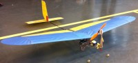
The aircraft I added the autopilot to has a fairly common design (cf pictures). The body is made of a carbon stick with a propeller at the end. The wings (the most critical parts) are made of light wooden sticks covered with paper and reinforced with laser-cut wooden surfaces. The actuators are made of wooden sticks covered with paper and are tied to servomotors by strings. The conception of the aircraft is way beyond my skills - it was built by model aircrafts amateurs at the University of Tokyo. I do not have the plans but if you're interested in viewing them please let me know.
Avionics
The model aircraft embeds the following electronics:
- a lithium battery (+ protected 5V regulator)
- a propeller with its driver
- servomotors (2 for the ailerons, 1 for the elevator, 1 for the rudder)
- an RF receiver that outputs PWM signals (to control the airplane with a remote control)
- an autopilot module (described below)
The servomotors and the propeller are controlled by PWM signals. Therefore, the actuators and the motors can be connected directly to the RF module and be controlled manually by the remote control.
Autopilot
The board has 3 microcontrollers :
- an ARM LPC2148 (3.3V but 5V tolerant)
- 2 PSoCs CY8C29466 (5V)
It also features :
- an accelerometer/gyroscope I2C module (sparkfun ITG3200/ADXL34)
- an altimeter module (PING 28015)
- a 3.3V regulator
- a voltage supervisor
The autopilot board "steals" its power source from an external 5V power source (therefore there is no 5V regulator on the board).
If you reuse this design, use a protected power source. Lithium batteries can be very dangerous so if you are not sure about your design please ask the supervision of an expert.
The ARM microcontroller runs the following loop :
- retrieve the target attitude (straight, circle, ...).
- read the raw data from the accelerometer/gyroscope module (by I2C).
- compute the current attitude.
- compute the servomotors' control value with PID algorithm.
- output servomotors' PWM signals.
PSoCs are connected between the ARM microcontroller, the RF module and the servomotors. They can be seen as PWM multiplexers. Their role is to transmit the good PWM signals to the servomotors (if manual mode, transmit the PWM signal from the RF module. Else, transmit the PWM signal from the ARM microcontroller). The PSoCs also have auxiliary roles.
PSoC n°1 has the following auxiliary loop :
- compute the current flying mode (there are 2 dedicated switches on the remote control, therefore two dedicated PWM inputs on the PSoC).
- transmit the current flying mode to PSoC n°2 and to the ARM microcontroller (by wire).
PSoC n°2 has the following auxiliary loop :
- read data from the altimeter and transmit them to the ARM microcontroller by I2C (because the altimeter module needs 5V and the ARM microcontroller is only 3.3V, it is simpler to use the 5V PSoCs) (note that this has not been implemented.)
PID control
Because of a mistake (ports with even numbers on the PSoCs cannot be used simultaneously as inputs on digital blocks), the autopilot module is not able to control both ailerons. The ailerons were therefore directly connected to the RF module and ignored by the autopilot module. This doesn't prevent the autopilot from working, since as written above, the rudder also has an effect on the roll - therefore we can control the roll by actuating the rudder. This way, we are not able to control the yaw independently, but as written above it is not a problem since the yaw is not "useful" for piloting.
There are 2 parallel SISO PID loops :
- the "pitch" loop, which has the "target pitch" as the input and the "elevator" as the output.
- the "roll" loop, which has the "target roll" as the input and the "rudder" as the output.
There is no software connection between those two loops. Coefficients have been set empirically. The motor is connected directly to the RF module (although a motor PWM route is available on the board).
To fly straight, we set a target for the pitch (e.g.20°) to prevent the airplane from losing altitude.
To fly in circles, we set a target for the pitch (e.g. 20°) and for the roll (e.g. 30°). The rudder will have an effect on the yaw, which will make the plane rotate and have a "parasitic" effect on the roll. With this method, we can reach the target pitch and roll, but the yaw is uncontrolled.
To fly in an 8-shape, we simply mix straight and circle positions.
Tests
The airplane was tested indoors only and showed good results. With PID coefficients too high, the airplane would swing dangerously but would stay steady enough to reactivate manual mode in time. With good PID coefficients, the attitude of the airplane was perfectly maintained.
Even if the attitude of the airplane is perfectly controlled, the motion of the airplane depends on many other parameters (motor speed, wind, ...). For a better "cruise control", improvements are needed : implementation of the altimeter, control of the motor speed, etc.
Note that if you are interested in reusing this design, you just need to reroute the PSoCs so that P0_i and P2_i (i = 0..7) are not simultaneously used as PWM inputs (it was my first time with PSoCs and I made that mistake on P0_2/P2_2 on PSoC 1, and P0_0/P2_0 on PSoC 2).
I also recommend that you revise the PCB layout to assure best thermal dissipation, trace clearance, etc.
Warning : the software is not completely verified/tested. The hardware is not 100% verified/tested either (possible voltage stability issues and/or thermal issues ?). Please use this with caution, in a safe environment.
Warning : as said above, Lithium batteries can be very dangerous. make sure you use protected and reliable components (high-temperature, high-voltage), avoid tantalum capacitors which can fail as short-circuit (use ceramic capacitors that match the capacitance/ESR specified in the voltage regulators' datasheet instead) and work in a safe environment. If you are not sure about your design, please ask the supervision of an expert.
https://www.elektormagazine.com/magazine/elektor-201505/27778
https://www.elektormagazine.fr/magazine/201505/27731
[Update 2015/09/15] Reorganized page and reuploaded sources. Will not touch this project from now.
Want to build a project?
Bring your design to life with the Elektor PCB Service, powered by Eurocircuits. Upload the project files and order professionally manufactured PCBs or assembled boards through a proven European production platform.
Supporting KiCad, Eagle, Gerber, and ODB++ formats, the service is suitable for everything from prototypes and validation builds to series production and volume manufacturing.
Made in Europe. Fast. Reliable. Professional.
Discussion (0 comments)