
PLµX: Programmable Logic Microcontroller on Linux [130494-I]
The PLµX Project is an effort to produce a Embedded Linux-based Programmable Logic Controller (PLC). PLCs were developed in the 1960s to replace the complex electrical relay circuits widely used for machine control in industrial automation. Users program PLCs to define a series of actions that a machine will perform.
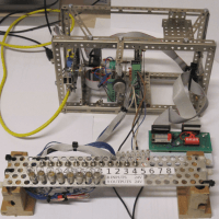
With GNUBLIN (embedded GNU / Linux board) and the aid of eight PCA9555 Port-Expanders the states of 64 inputs can be monitored and 64 outputs can be driven.
The PLµX Ladder Diagram Editor is designed to allow you to easily prepare a PLC program by simply placing blocks.
Ladder diagrams, which are in many ways similar to relay logic diagrams, are frequently used to graphically generate programs.
When the instructions in the program are executed, the states of the inputs are monitored, depending on these states, various outputs are set either High or Low.
Raspberry Pi simple PLC, 8 outputs (24 Volt) controlled by 1 analog input.
Raspberry Pi Simple PLC: Analog inputs implemented.
How to connect the hardware to the raspberry board.
Creating a first Ladder Diagram.
RPIsPLC first run.
A first attempt to implement the PlµX project into a Raspberry Pi single-board computer (under construction).
Update: january, 20, 2014
For coupling the board to various types of devices, relays and sensors an expansion board is needed.
24V interface board with 8 isolated inputs and outputs created for the Gnublin board. More information:
Update: November, 20, 2013
With four extra GNUBLIN ADC modules 32 analog inputs can be monitored.
Update: July, 27, 2013
Alarm Clock function implemented.
Update: July 1, 2013
Ladder diagram editor new version.
GNUBLIN board new software version.
Test 02: Timers and counters implemented.
Update: 16 juni 2013
Test interface for 24 inputs and outputs.
First test example: press one button (input) and 16 leds (16 outputs) light on.
Want to build a project?
Bring your design to life with the Elektor PCB Service, powered by Eurocircuits. Upload the project files and order professionally manufactured PCBs or assembled boards through a proven European production platform.
Supporting KiCad, Eagle, Gerber, and ODB++ formats, the service is suitable for everything from prototypes and validation builds to series production and volume manufacturing.
Made in Europe. Fast. Reliable. Professional.
Discussion (3 comments)