
Quizmaster console for 6 players
Hands on the buttons, who was 1989 worldchampion .... The player who presses first may answer; when the buzzer sounds, the answering time is over.
Hardware
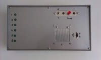
The heart of the console is a microcontroller board. I use Elektor board 160465-1 (see https://www.elektormagazine.nl/magazine/elektor-201711/40840; on the photo a prototype of this board is shown), but with a different program in the PIC. Some additional components are required for operation, indication and audio output. These are mounted "free hanging" as the photos show.Remark: because the reset pin of the PIC is the physical reset, the program will only run if input K5-1 is at +12V.
The console is powered by an external 12V supply with 1A or by a car accumulator. The outputs of the console are capable of delivering 0.5 A for a player indication lamp, so a fuse of between 0.5A and 1A is adequate. Don't omit the fuse if you are planning to power the unit from an accumulator!
As shown on the photo, I use 6.3 mm stereo jack connectors for the players, but any other 3-way connector can be used.
Connector "L" on the photo is used to power an additional lamp (in my case 12V, 3W), which shows "game active".
Attention: the common wires of the player and "L" connectors are at +12V, so it may be good idea to use isolated connectors. This will eventually prevent a blown fuse.
For the audio an internal speaker can be used. Don't connect a 4 or 8 ohm speaker directly to the output of the board, because of the limited output power available, but also because 12Vpp is a lot of noise. I use a small 300 ohm speaker from my junk box which performs very good; an 8 ohm speaker with a 5:1 or 10:1 transformer will do as well. The speaker can be switched off with S3, in which case an external amplifier can be used. The internal speaker or the external output are not essential and one of them can be omitted.
The player stations only contain a button (use a stable one!) and a LED and/or any other visual indication (max. 6W). I use coloured 12V, 3W bulbs from a christmas string. On the lower left part of the schematic my version of a player station is shown.
Program
Although I am in principle a c-programmer this program has been written in assembly language. The source and the hex-file (for a PIC16F628A) can be downloaded. The program can also be used for a PIC16F627(A).Course of the standard program:
- After canceling the reset, it is first tested whether player buttons have been pressed. If so, an indication is shown ("hands from the buttons") and the game will not start before all buttons are up. The actual program shows no indication which player has pressed the button. This test can be skipped.
- Then the response time starts running (adjustable between 2 and 120 sec, default 10 sec). When the time elapses without a player responding, a buzzer sounds and the time stops. The same happens when the quizmaster presses the stop button. All player keys will be blocked until the next reset.
- When a player presses the button in time a siren will sound, the corresponding LED on the console and the player lamp will light and the buttons of all other players are blocked.
- Another (or the same) player can press to answer the question after a delay (parameter 6) if the first one is too late.The buzzer will sound to indicate the timeout. As soon as the master lamp is lit another player can press. This option is skipped in the default settings.
- To start a new game, the console must first be reset by the quizmaster. The reset can be used to lock the console for a while before starting a new game.
The following settings can be changed in setup mode (1-6) or by rewriting EEPROM values (1-8):
- Player timeout in 0,5 sec steps (2 .. 120 sec; < 2 sec = no timeout; default 10 sec)
- Test on active player buttons at start (0=none, 1=stop with buzzer and LED, 2=stop with LED, 3=wait with LED; default 3)
- Operation of quizmaster key (0=none, 1=start timeout, 2=stop game, 3=both; default 2)
- Sound output (0=logical level, 1=buzzer and beep, 2=buzzer and siren; default 2)
- Same player can press again (0=no, 1=yes, 2=after buzzer; if timing6 > 0; default 0)
- Delay before next player can press a key (2 .. 120 sec; < 2 sec = no second chance; default off)
- Duration of the buzzer (0,5 .. 8 sec, default 1.5 sec)
- Duration of the bell/siren (0,5 .. 8 sec, default 2.5 sec)
The timing (settings 1 and 6) is setup by pressing the key as many seconds as the resulting time should be. If the key is pressed less than 2 sec, no timeout is set (=forever). After setting a timing setup mode is stopped.
The other paramers are shown by lighting the corresponding player lamp (0=player 1, 1=player 2, etc.) at the first keypress and incremented by any additional keypress.
Build This Project
Bring this design to life with the Elektor PCB Service, powered by Eurocircuits. Upload the project files and order professionally manufactured PCBs or assembled boards through a proven European production platform.
Supporting KiCad, Eagle, Gerber, and ODB++ formats, the service is suitable for everything from prototypes and validation builds to series production and volume manufacturing.
Made in Europe. Fast. Reliable. Professional.
Discussion (0 comments)