
Thyristor used as a temperature sensor and switch
This circuit detects if the temperature of an object became too high. The thyristor is mounted on the object that has to be temperature monitored. If the object get's too hot the thyristor switches and engages an indicator LED, maintaining that state until a reset is done. See movie(link) for operation.
Introduction:
This circuit uses one thyristor functioning as a combined sensor, switch and memory. In addition you only need 3 resistors and a LED.
It can be used for applications described below but it is also meant as an "electronic puzzle" to show alternative use of common components.
The thyristor should be mounted on the object that has to be temperature monitored, like a heatsink for example, using it's mounting hole on the tab. Now if the object get's above the selected temperature for some moment in time the thyristor switches on and engages an indicator LED, staying in that state until a reset is done. This way it can be even detected later that the object temperature became too high.
Reset can be done by shortly interrupting the supply or by adding an breaking pusbutton in series with the LED.
Concept of this circuit idea:
The gate input of a thyristor has a diode-like structure (PN junction between gate-kathode).
The voltage drop across a diode decreases with increasing temperature.
Therefore the trigger treshold voltage of a thyristor lowers when temperature rises.
If we now apply a fixed constant voltage to the gate, with such a value that it does not trigger at room-temperature, a high enough temperature will make it trigger.
Switch temperature can be selected by choosing the two gate resistor values and/or the voltage driving this divider.
This is not a very accurate circuit, you could easily be 10 celsius off, but it can be good enough to function as a thermal overload indicator for something like a power amplifier. If you have the thyristor switching a relay it could turn into a protection circuit by switching off the load for example. The circuit shown here switches the LED at approximately 50 celsius.
Details:
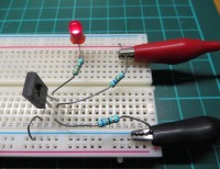
The circuit was build with a quite standard thyristor: the C106D (available for 0.4 Euro). Using the resistor values from the schematic and using a 5V supply, the applied gate voltage in the circuit measured 545mV in the "off" state. When the LED is switched on, this jumped up to 650mV because of the latching behavior.
If you only have a TRIAC available, that also can be used, just check with your multimeter which pin (M1 or M2) forms a diode with the gate.
A TIC206 was tested and worked fine, it had a diode from gate to M1, the 560 ohm resistor had to be changed to 470 ohm.
The movie shows the switching, hold and reset behaviour
This circuit uses one thyristor functioning as a combined sensor, switch and memory. In addition you only need 3 resistors and a LED.
It can be used for applications described below but it is also meant as an "electronic puzzle" to show alternative use of common components.
The thyristor should be mounted on the object that has to be temperature monitored, like a heatsink for example, using it's mounting hole on the tab. Now if the object get's above the selected temperature for some moment in time the thyristor switches on and engages an indicator LED, staying in that state until a reset is done. This way it can be even detected later that the object temperature became too high.
Reset can be done by shortly interrupting the supply or by adding an breaking pusbutton in series with the LED.
Concept of this circuit idea:
The gate input of a thyristor has a diode-like structure (PN junction between gate-kathode).
The voltage drop across a diode decreases with increasing temperature.
Therefore the trigger treshold voltage of a thyristor lowers when temperature rises.
If we now apply a fixed constant voltage to the gate, with such a value that it does not trigger at room-temperature, a high enough temperature will make it trigger.
Switch temperature can be selected by choosing the two gate resistor values and/or the voltage driving this divider.
This is not a very accurate circuit, you could easily be 10 celsius off, but it can be good enough to function as a thermal overload indicator for something like a power amplifier. If you have the thyristor switching a relay it could turn into a protection circuit by switching off the load for example. The circuit shown here switches the LED at approximately 50 celsius.
Details:
The circuit was build with a quite standard thyristor: the C106D (available for 0.4 Euro). Using the resistor values from the schematic and using a 5V supply, the applied gate voltage in the circuit measured 545mV in the "off" state. When the LED is switched on, this jumped up to 650mV because of the latching behavior.
If you only have a TRIAC available, that also can be used, just check with your multimeter which pin (M1 or M2) forms a diode with the gate.
A TIC206 was tested and worked fine, it had a diode from gate to M1, the 560 ohm resistor had to be changed to 470 ohm.
The movie shows the switching, hold and reset behaviour
Want to build a project?
Bring your design to life with the Elektor PCB Service, powered by Eurocircuits. Upload the project files and order professionally manufactured PCBs or assembled boards through a proven European production platform.
Supporting KiCad, Eagle, Gerber, and ODB++ formats, the service is suitable for everything from prototypes and validation builds to series production and volume manufacturing.
Made in Europe. Fast. Reliable. Professional.
Discussion (4 comments)