
Valve hybrid headphone amplifier
Hi guys, Let's go back in old school electronics. What about integrating a valve triode in a project, the same as our grandfathers used to hear before the invention of the transistor ?
Hi guys, Let's go back in old school electronics. What about integrating a valve triode in a project, the same as our grandfathers used to hear before the invention of the transistor ?
In audiophile world, everybody talk about "the sound of tube", with its "color" and its "heat". I wanted to taste this famous sound but valve based power amplifiers are often quite expensive and use high voltage rails (from 130 to 190Vdc). It's a bit too difficult for a first try.
To keep cost to a lower level, I decided to build a valve based headphone amplifier, but instead of many designs found on the web, this one would be updated with modern parts.
But wait, what is a "headphone amplifier" ? For what ??? For who ???
Many today's audio devices are designed to drive low impedance headphones (from 8 to 32 ohms), corresponding to the majority of "cheap" headphones found on the market. But high-end headphone are usually around 120 to 600 ohms and need higher voltages to be driven, which an iPod's or a computer's output can't supply. Furhermore, some portable devices have low quality amplifier stages but have better quality line outputs. This is the case of iPods or computer's integrated soundcards. For those situations, a headphone amplifier (driven by the line out) would deliver a better sound, even if you only use a mid-range headphone.
This amplifier is an hybrid one, using a MOSFET for its output. This choice avoids using hard to find transformers. It works in class A, which is the best choice for audio fidelity, but also means high dissipated power... Hopefully, as we only need a few milliwatts, global dissipation will only be 12W... ;-) Just enough to heat your hands while working on your computer during long winter evenings. The valve's heater also needs around 6V and 300mA to work. I designed a small switching supply to lower heat dissipation. Purists will say that it's a nonsense in an audio design... We will see...
I integrated a tone and volume control to adjust sound to everyone's convenience. I also added a soft-start supply to avoid stress and 'pop' noise on power up.
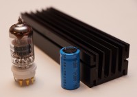
The whole design fits on a 150*82mm board, placed in a case formed by two big heatsinks and some aluminium plates. The tube is of course visible and can easily be changed for "tube-rolling" adepts.
The schematics and layout are ready, PCB is in production and prototype will wake up in the next days, Stay in touch !
Update 2013-11-21 : Prototype's first run
After correcting some layout mistakes, I could have it producing its first baby cries. I have to say I'm a bit disappointed. Potentiometers produce a horrible sound when turned. Bias setting is very unstable, it depends on the volume level applied... "hum" level is horrible, and the whole box is very sensitive to cell phone's wave, that's what I wanted to avoid... However I had it singing, but I wasn't able to distinguish a better sound compared to my silicium headphone amplifier. The sound appears to have a narrower bandwidth, like if it had been recorder on an old vinyl disk...
I don't want to spend much time on this project, it was a try, not successed, let's switch to something else...
Build This Project
Bring this design to life with the Elektor PCB Service, powered by Eurocircuits. Upload the project files and order professionally manufactured PCBs or assembled boards through a proven European production platform.
Supporting KiCad, Eagle, Gerber, and ODB++ formats, the service is suitable for everything from prototypes and validation builds to series production and volume manufacturing.
Made in Europe. Fast. Reliable. Professional.
Discussion (1 comment)