
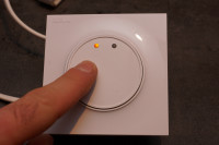
Wall-mounted tactile switch [130272]
This project is a multi-configuration capacitive switch, designed to be mounted on a wall in a standard switch box and powered by mains.Features :
This project is a multi-configuration capacitive switch, designed to be mounted on a wall in a standard switch box and powered by mains.
Features :
The system is divided in 2 (or 3 boards). One will hold power components and power headers. The other one will hold capacitive electrodes and small signal electronics.
- Classic electromechanical relay : Not compatible with the low power requirement. It would need many dozens of mAmps when closed, and in a two way configuration, this current would be wasted even if the light is off.
- Bistable relay : Interesting to reduce current needs. The simplest option in switching, but the coil driving stage would have been more complicated. As switching draws hundreds of mAmps during a few milliseconds, I didn't want to design a strong power supply wasting power most of the time. I was thinking of using a big bulk capacitor to drive the relay. The time needed to charge it again depends on current available at the supply... The cheapest bistable relays found on Farnell's website was at 4,5€, twice for a dual switch configuration... Too expensive
- Triac (SCR) : Old school design... SCR have heating issues and also need around 10mA to stay closed. They also could have latching issues when lightly loaded, which is the case with actual economical lamps.
- I finally chose to use a MOSFET as switching part because of its very low current requirements, its unexpensive price, and its better efficiency (less than 0,5W loss when driving 200W). Mosfets can only work with positive supplies, so a full bridge diode rectifier is added. With this configuration, I can keep the whole current requirements less than 0.1W, even when load is ON.
Update 2013-10-20 : Hardware debugging - Capacitive board
Hi folks !
I've finally received the prototype PCB and completed the assembly. I already have many details to improve, some footprints mistakes, but nothing really worrying at the moment.
I've worked on the capacitive board at the moment, supplied by a 9V battery. The capacitive sensing aroung AT42QT1010 works perfectly! It's even able to detect an approaching finger within a few millimeters from the sensor.
The momentary switch mode works great as is. However, I had triggering issues when trying the "toggle button" mode. The flip flop didn't want to lock. Instead of a toggle button, I still had a momentary action... Strange flip flop...
The datasheet says the rise time of inputs shall be better than 10ns/V. Far far quicker than the R/C networks formed by R21/C11 allows. That explained the triggering issues. I tried to remove the capacitor, but... Still didn't work! What the hell there???
I discovered the AT42QT1010 had a "heart beat" function. It tri-states its output periodically during 15µs. Without any capacitor on the output, it gives a nice low level, brief but sufficient to change flip flop output.
The solution was then to shunt R21, keep a small capacitor for C11. Its value had to be enough to maintain signal during heart beat, but the lowest possible to keep rise time acceptable.
With a 1nF cap, the heart beat showed only 500mV drop, but the rise time is around 150ns. Far more than the 30ns allowed, but it works anyway.
I'll change the schematics using a more classical SN74HC74 dual flip flop wich accepts slower signals while being cheaper and easier to find.
Next step: power board testing. Keep in touch!
Update 2013-10-20 : Hardware debugging - Power... :-(
I spent my last week debugging the power board. The resistive power supply from mains works well, nothing gets hot as expected, all good there..
The MOSFET load switching works also great, I could stack both boards and make the whole electrical chain lighting on and off a 230V 50W desktop lamp. That sounds great !
However... I discovered that when the second channel was activated, the lamp lit on at half power... After having checked the electrical levels, it is in fact due to the design of the power switching itself. The MOSFET through the diode bridge drive works for one channel, but an electrical path exists between both of them. Negative half waves are blocked but positive ones can still go from ch1 to ch2, that explains why my lamp lit even though it wasn't expected to !
I don't have any solution to solve this issue.
Changing the design for a single switch would have been a simple solution, but it isn't satisfying. A modern house has many two-way switches or dual switches in a same housing. Limiting to a single one would be unusable...
I took out the drawing board and looked for another solution :
TCR need too much current to be maintained in hold position with modern lamps, that can not work
The latching relay is the best alternative for me. I found small bistable relays at only 3€ on farnell's website, which require 200mW for triggering during only 20ms. That's finally less than I thought and I found a little trick to keep idle power under 30mW... but i'll tell you that next time ;-)
Update 2013-11-06 : Throw away those MOSFETS and change for latching relays
As told previously, I ordered two small latching relays to make some tests. Those are interesting parts in my design as they only need power during state change and keep their position undefinitely without any power !
However, their driving is a bit more difficult than standard relays. When powered with a positive voltage, the coil goes in one position and we need to apply an opposite (negative) voltage to go back in the other position. I simply added a big electrolytic capacitor to form a high pass filter and generate the negative supply on falling edges. The capacitance is adjusted to supply only the needed energy to trigger. As the relay current is much higher (~20mA) than the power supply can provide (~2mA 15Vdc), a big bulk capacitor avoids too much voltage drop. With this design, the power drawn from mains is kept very small (less than 0.05W continuous for the whole design).
A small "power level translator" is made of a MOSFET gate driver. This driver is able to drive much current with a very low power command, perfect for this application.
The new layout is ready for manufacture. As the board is made of three parts, I included the manufacturing panel based on Eurocircuits recommendations.
Update 2013-12-21 : 2nd generation prototype
I've just finished soldering the new prototype. Capacitive sensing board works now perfectly with flipflop modification. All is working great now !
I'm just going to try the power board, but i'm very confident with it...
I keep you in touch soon ! :-)
Update 2013-12-22 : All works great !
The power board works perfectly too ! I just had to lower sensitivity of capacitive board by adjusting C9 and C13 from 10n to 4,7nF.
Mains RMS current is at 7,17mA. As virtually no power is lost in C5, the total power is Irms*Vz = 7.17*12 = 0,086W. Goal attained ! :-)
Want to build a project?
Bring your design to life with the Elektor PCB Service, powered by Eurocircuits. Upload the project files and order professionally manufactured PCBs or assembled boards through a proven European production platform.
Supporting KiCad, Eagle, Gerber, and ODB++ formats, the service is suitable for everything from prototypes and validation builds to series production and volume manufacturing.
Made in Europe. Fast. Reliable. Professional.
Discussion (1 comment)