Heating System Monitor
Add-on for thrifty consumers
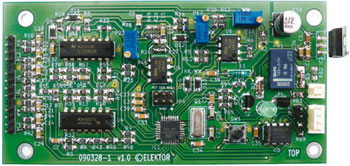
Usually you can tell how much energy your heating system has consumed by checking your utilities bill, but what if you want to know how much heat it actually delivered? This clever design from one of our readers measures the actual heat output and doesn’t require any modifications to your central heating system. It also has a built-in control function for the circulation pump, which helps you reduce your environmental impact and keep your bank balance healthy.
Materials
Gerber file
CAM/CAD data for the PCB referred to in this article is available as a Gerber file. Elektor GREEN and GOLD members can exclusively download these files for free as part of their membership. Gerber files allow a PCB to be produced on an appropriate device available locally, or through an online PCB manufacturing service.
Elektor recommends the Elektor PCB Service service from its business partner Eurocircuits or AISLER as the best services for its own prototypes and volume production.
TIP: your first PCB at AISLER is free up to €30 with using the coupon code ELCCBB at checkout.
The use of our Gerber files is provided under a modified Creative Commons license. Creative Commons offers authors, scientists, educators and other creatives the freedom to handle their copyright in a more free way without losing their ownership.
Component list
Resistors (SMD 1206)
R2 = 1kOhm
R3,R4,R7,R8,R9,R10,R13,R14,R15,R21,R43,R46,R47,R48,R52,R56,R57,R59,R60,R64,R65 = 10kOhm
R5,R12,R16,R17,R20,R27,R36,R38,R42,R50,R54,R58,R70 = 100kOhm
R6,R49,R51 = 390kOhm
R11,R18,R19,R61 = 1MOhm
R22,R23,R26,R37,R39,R44,R53 = 2.2kOhm
R29 = 1.5kOhm
R30 =47Ohm
R32,R33,R34,R35,R45,R55 = 68kOhm
R62 = 1Ohm
R63 = 150Ohm
R69 = 120Ohm
P17,P18 = 500Ohm (trimpot type 64Y)
P23 = 1kOhm (trimpot type 64Y)
Capacitors (SMD 1206 except C16)
C1 =330nF
C2,C3,C23,C32,C33,C34,C35 = 100nF
C6,C7,C13,C14,C20,C21,C25,C24,C28 = 470nF
C15 = 1µF
C16 = 470µF 16V
C26,C27 = 22pF
C36,C37,C38,C39 = 10µF 16V
Inductors
L1 = 10µH
Semiconductors
U4,U7 = TLC2264 (DIP14)
U5,U6 = LM358 (DIP8)
U8 = MAX487 ECPA (DIP8)
IC1 = ATmega328-20AU (TQFP32-08), programmed, Elektor no. 090328-41
IC2 = 7805 (TO220)
T1,T2 = BC550C (TO92-EBC)
D1,D2 = 1N4148 (SOD106-R)
VL,VL2,RL,RL2,WW,KK = KT110, KT210, KTY11, KTY21, KT130, KT230, KTY13 or KTY23 (SOD23 or TO92-mini, resp.)
D4 = LED (5 mm)
D9, D11, D12, D13, D14 = SD103BW (DO-214BA)
Miscellaneous
Q1 = 14.7456MHz quartz crystal (HC49U-S)
K1 = relay, bistable (TQ2-L2-12V)
SW1 = micro pushbutton (lead pitch 5mm)
JP4 = 6-pin (2x3) pinheader (lead pitch 2.54mm)
JP3 = jumper (2.54mm)
P24 = 4-pin pinheader and plug (lead pitch 2.54 mm)
P25 = 2-pin pinheader and plug (lead pitch 2.54 mm)
VL,VL2,RL,RL2,WW,KK = 14-pin pinheader and plug, gold-plated (lead pitch 2.54mm) (see text for English labels S, S2, R, R2, CC, HH)
Microphone cable = ML108 (1 x 0.08 mm)
Heat shrink sleeve (1.6mm and 3.2mm)
G1= Aluminium enclosure, like Teko type B4 (143x72x43mm)
PCB standoff (M3)
Nuts (M3)
LED clip (5 mm)
PCB, no. 090328-1
Discussion (0 comments)