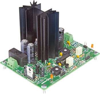
Unilab Mk. 2
0–30 V, 3 A compact switch-mode lab power supply
Continue reading this Elektor article?
- Try a digital membership (Green) for 4 months for only 1.75 per month.
- Access to Elektor archive, digital magazines and over 5,000 Gerber files.
- Independent reviews and high-quality DIY electronics projects. Inspiration and solutions for all your electronics challenges.
- A community of active e-engineers – from beginners to professionals.
Materials
Gerber file
CAM/CAD data for the PCB referred to in this article is available as a Gerber file. Elektor GREEN and GOLD members can exclusively download these files for free as part of their membership. Gerber files allow a PCB to be produced on an appropriate device available locally, or through an online PCB manufacturing service.
Elektor recommends the Elektor PCB Service service from its business partner Eurocircuits or AISLER as the best services for its own prototypes and volume production.
TIP: your first PCB at AISLER is free up to €30 with using the coupon code ELCCBB at checkout.
The use of our Gerber files is provided under a modified Creative Commons license. Creative Commons offers authors, scientists, educators and other creatives the freedom to handle their copyright in a more free way without losing their ownership.
Extra info / Update
Max. output current: 3 A (voltage limiting at 3.2 A)
Voltage variation from no load to 3 A: 0.17 V
Switching frequency 260 kHz
Maximum ripple (260 kHz): 120 mVpp
Nominal input voltage: 36–38 V
Automatic output shutdown when Vin < 34.2 V
Efficiency at 30 V / 3 A out: 93%
Efficiency at 5 V / 3.1 A out: 80%
Compact PCB layout
Component list
Resistors
Default: 5%, 0.25 W
R1,R11,R28 = 10kOhm
R2,R34 = 100Ohm
R3,R21,R30 = 1kOhm
R4,R9 = 20kOhm, 1%
R5,R24 = 18kOhm
R6,R19 = 2.00kOhm, 1%
R7,R17,R18 = 200Ohm, 1%
R8 = 1.2kOhm
R10 = 220kOhm
R12 = 330Ohm 5%, 5W
R13,R14,R15,R16 = 0.1Ohm, 5% 0.5W
R20 = 1.8kOhm
R22,R29 = 47kOhm
R23 = 470Ohm
R25 = 8.2kOhm
R26 = 10MOhm
R27 = 100kOhm
R31 = 270Ohm
R32 = 820Ohm
R33 = 36kOhm, 1%
P1 = 22kOhm trimpot, horizontal
P2 = 220Ohm trimpot, horizontal
P3,P4 = 10kOhm potentiometer, linear
Capacitors
C1,C2 = 220µF 63V, radial, 5mm pitch, 10 mm diam.
C3,C7 = 2.2µF 50V, ceramic Y5V, 0.2’’’pitch
C4 = 10nF 100V, ceramic X7R, 0.2’’’pitch
C5 = 100pF 100V, ceramic h C0G/NP0, 0.2’’’pitch
C6 = 1nF 100V, ceramic X7R, 0.2’’’pitch
C8 = 100µF 63V, radial, 5mm pitch, 10mm diam.
C9 = 4.7nF 50 V, ceramic X7R, 0.2’’’pitch
C10 = 2.2nF 100V, ceramic X7R, 0.2’’’pitch
C11 = 1µF 63V, 5%, MKT, 5 or 7.5mm pitch
C12 = 2.22µF 50V, 5%, MKT, 5 or 7.5mm pitch
C13,C14 = 100nF 50V, ceramic X7R, 5mm pitch
C15,C16,C17 = 10µF 50V radial, 2mm pitch, 5 or 6.3mm diam.
C18 = 220pF 200V, ceramic C0G/NP0, 0.2’’’pitch
Inductor
L1 = 22µH, 15%, 11A, 0.014Ohm, 23.9 or 29.3mm pitch (e.g. Murata 1422311C)
Semiconductors
D1 = BZX55C30, 30 V, 0.5W zener diode
D2 = MBR1045, TO-220AC
LED1,LED2 = LED, green, 3mm
T1 = J175_D26Z, TO-92
T2 = BS170, TO-92
IC1 = LM2677T-ADJ, TO-220-7
IC2 = LM6134BIN/NOPB, MDIP-14
IC3 = LM317, TO-220-3
Miscellaneous
K1,K2 = 2-way PCB screw terminal block, 0.2’’ pitch
K3 = 2-pin pinheader, 0.1’’ pitch
P3,P4 = 3-pin pinheader, 0.1’’ pitch
F1 = 3,15 AT (slow), with fuseholder and cap, PCB mount, 20 x 5 mm, 500 V
HS1 = heatsink, PCB mount, 2.6K/W, 1 inch mounting pin distance (e.g. Aavid 530002B02500G)
Thermal isolation set for D2, comprising washer and ring (e.g. Multicomp MK3306/S)
PCB # 150161-1
Discussion (0 comments)