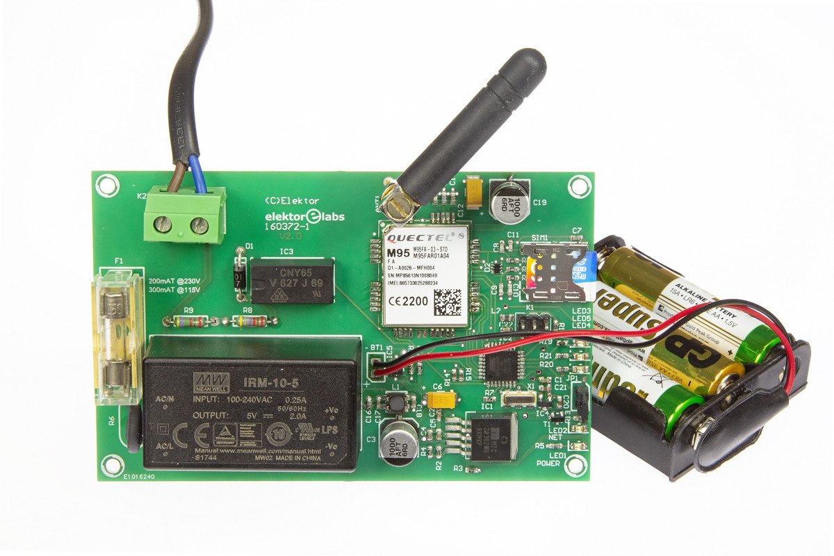
Power Outage Detector with Text Messaging
Detects and reports power outages (even short ones)

Gerber file
CAM/CAD data for the PCB referred to in this article is available as a Gerber file. Elektor GREEN and GOLD members can exclusively download these files for free as part of their membership. Gerber files allow a PCB to be produced on an appropriate device available locally, or through an online PCB manufacturing service.
Elektor recommends the Elektor PCB Service service from its business partner Eurocircuits or Eurocircuits as the best services for its own prototypes and volume production.
The use of our Gerber files is provided under a modified Creative Commons license. Creative Commons offers authors, scientists, educators and other creatives the freedom to handle their copyright in a more free way without losing their ownership.
Components
The BOM (Bill of Materials) is the technically exhaustive listing of parts and other hardware items used to produce the working and tested prototype of any Elektor Labs project. The BOM file contains deeper information than the Component List published for the same project in Elektor Magazine. If required the BOM gets updated directly by our lab engineers. As a reader, you can download the list here.
Want to learn more about our BOM list? Read the BOM list article for extra information.
Component list
Component List
Resistors
Default: 1%, 0.1W, 50V, SMD 0603
R1 = 10kΩ
R2 = 110kΩ
R3,R19 = 470Ω
R4 = 43kΩ
R5,R13,R20,R21 = 1kΩ
R6 = NTC 80R B57236S0800M000, Epcos
R7 = 4.7kΩ
R8,R9 = 47kΩ, 5%, 0.6W, 250V, axial leads (for 115VAC operation replace R9 by a wire strap)
R10,R11,R12 = 22Ω
R14,R15 = 100kΩ
R16 = 470kΩ
R17 = 1MΩ
Inductors
L1 = ACM4520-231-2P-T common-mode filter
L2 = BLM21AJ601SN1D, 10µH / 600Ω at 100MHz, SMD 0805
Capacitors
Default: 50V, ceramic, SMD 0603
C1,C2,C4,C5,C7,C13,C16,C17,C18,C22 = 100nF
C3,C19 = 1000µF 10V, electrolytic, SMD, radial, 8mm diam.
C6,C12 = 100µF 16V, tantalum electrolytic, SMD 2312
C8-C11,C15 = 33pF, C0G/NP0
C14 = 10pF, C0G/NP0
C20,C21 = 1µF 10V
Semiconductors
D1 = 1N4007 diode, 1000V/1A
D2 = SMF05CT2G protection diode array
LED1 = yellow, SMD 0805
LED2,LED5 = green, SMD 0805
LED3 = red, SMD 0805
LED4 = orange, SMD 0805
T1 = 2N7002, n-channel MOSFET, SOT-23
IC1 = MIC29302WU TR, low-drop voltage regulator, adjustable
IC2 = ATmega328P-AU, microcontroller, programmed 160372-41
IC3 = CNY65, optocoupler
IC4 = MCP1700T-2802E/TT, low-drop voltage regulator, 2.8V
IC5 = LTC4413, dual fast diode / voltage changeover
Miscellaneous
MOD1 = AC/DC converter module, 5V/2A (Meanwell IRM-10-5)
MOD2 = Quectel M95 GSM module
X1 = 8MHz ceramic resonator, Murata CSTCC8M00G53-R0
SIM1 = micro SIM card socket, SMD (Molex 78723-1001)
ANT1 = SMA socket, PCB mount (Molex 73391-0070)
Matching GSM antenna with SMA plug (RF Solutions ANT-GHEL2R-SMA)
JP1 = 2-pin pinheader, vertical, 0.1" pitch
Jumper for JP1
F1 = fuse, T, 5×20mm, 315mA (230V) or 620mA (115V)
Fuse holder for F1 (Multicomp MC000827)
Fuse cover for F1 (MC000833) *
K1 = 6-pin (2×3) pinheader, vertical, 0.1" pitch
K2 = 2-way screw terminal block, 630V, 0.3" pitch
BT1 = battery holder for 3× AA cells
Clip for BT1
PCB 160372-1 V2.1


Discussion (5 comments)