When it comes to choosing the right type of accelerometer, understanding product capabilities and assessing test conditions are essential for choosing the right solution. The following is a primer on the options to consider for meeting all the necessary measurement requirements.
When it comes to researching, developing, and testing products in harsh and complex environments, accelerometers can provide invaluable data. But as with most engineering activities, choosing the right tool may have serious implications on the measurement results. This is a particular concern for engineers involved in high-g impact and shock testing where intense temperature, vibration, and shock from munitions and impact testing creates additional challenges in delivering precision results.
Since each accelerometer sensing technology has its advantages and compromises, choosing the right type of accelerometer requires an understanding of the various options and their technical capabilities. It also requires an analysis of the circumstances and parameters in which the accelerometer must perform.
To help choose the right accelerometer, the following is a primer on the options to consider for meeting all the necessary measurement requirements. In addition, a list of critical questions is provided for a hypothetical situation — in this case, measuring over 50 g — as a means to demonstrate the type of critical issues that also should be addressed to inform the decision-making process.
Consideration One: Understanding Accelerometer Classes
In general, there are two classes of accelerometers: AC-Response and DC-Response. In an AC-response accelerometer, as the name implies, the output is AC coupled. An AC-coupled device cannot be used to measure static acceleration such as gravity and constant centrifugal acceleration. It is only suitable for measuring dynamic events.
Alternatively, a DC-response accelerometer is DC-coupled and can respond down to 0 Hz. As a result, it can be used to measure static, as well as dynamic, acceleration. However, measuring static acceleration is not the only reason a DC-response accelerometer should be considered.
For real-world applications, the majority of vibration studies require the knowledge of acceleration, velocity, and displacement — the important variables that engineers seek in designing or validating a structure. Generally speaking, the g value provides a good reference, but velocity and displacement are the variables needed in most design calculations. To derive velocity and displacement from the acceleration output, the signal from the accelerometer is integrated and double integrated, respectively, in the analog or digital domain.
This is where an AC-response accelerometer may run into trouble. It has an intrinsic limitation imposed by its RC time constant and therefore encounters problems when needing to track slow motions. Conversely, a DC-response device presents no such problem (Figure 1).
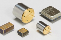
Figure 1: Embedded Accelerometers — TE
manufactures various board-mounted
silicon MEMS accelerometers
and piezoelectric accelerometers.
Consideration Two: Looking at Accelerometer Technologies
The most common AC-response accelerometers use piezoelectric elements for their sensing mechanism. Under acceleration, the seismic mass of the accelerometer causes the piezoelectric element to “displace” a charge, producing an electrical output proportional to acceleration. Electrically, the piezoelectric elements look like a source capacitor with a finite internal resistance, typically in the order of 109 Ω. This forms the RC time constant which defines the high-pass characteristics of the device. For this reason, piezoelectric accelerometers cannot be used to measure static events. In addition, because piezoelectric elements also can be natural or man-made, they come with varying degrees of transduction efficiency and linearity characteristics.
Two types of piezoelectric accelerometers are available on the market: Charge Output Type and Voltage Output Type. Available in very small footprints, they are suited for dynamic measurements in lightweight structures.
Charge Mode Piezoelectric sensors are based on lead zirconate titanate ceramics (PZT), which offer very wide temperature range, broad dynamic range, and wide bandwidth (usable to greater than 10 kHz). When housed in a hermetic, welded metal case, a charge mode accelerometer can be considered one of the most durable sensors because of its ability to tolerate hostile environmental conditions. Due to the wide operating temperature range of piezoelectric ceramics, some charge mode devices can be used from -200°C to +640°C and beyond. They are especially suitable for use in vibration measurements at temperature extremes, such as in turbine engine monitoring.
The other type of piezoelectric accelerometer provides voltage output, accomplished by incorporating the charge amplifier inside the housing of the accelerometer. Unlike a charge mode device that only contains ceramic sensing element(s), a voltage mode device includes a microelectronic circuit which limits the operating temperature of the device to the maximum operating temperature of the electronics, usually topping at +125°C. Some designs push the limit to +175°C, but this presents compromises elsewhere in the performance envelope (Figure 2).
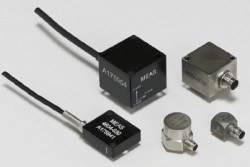
Figure 2: Plug & Play Accelerometers — TE’s
packaged accelerometersfeature DC (static)
and AC (dynamic) response in a wide
measurement range and a convenient
user interface.
Choosing the right accelerometer also requires an assessment of the conditions in which it will need to perform — particularly if those conditions are harsh and complex. For example, here are five basic questions to ask when planning to measure over 50 g.
What is the expected dynamic range to be measured or tested? When using an accelerometer, there should be enough of a margin to ensure the test results are usable and the measurement range does not exceed the FS output of the accelerometer. If, for example, the g-force is higher than the accelerometer’s upper limit, this may clip the signal and render the test results useless. By best practice standards, plan for results to fall within 30-40% of the device’s full-scale range, and never less than 10%.
What’s the measurement bandwidth? The measurement bandwidth will depend on many factors, specifically the type of test and the impact surface. For example, if measuring a drop on a soft landing, a narrow bandwidth may be fine. But if looking to measure peak g’s in high-impact tests, like munitions and automotive crashes, a wider bandwidth will be needed.
How will the sensor be mounted during testing? It’s important to know how to install the accelerometer, as well as where it will be placed. For best results, accelerometers should be mounted rigidly to the apparatus. And while there are some materials, like cyanoacrylate that can be used to adhere an accelerometer to a device, most epoxies and glues should be avoided, as they’ll serve as extra dampening agents and absorb energy before it can be registered by the accelerometer.
In which conditions will the test be conducted? All accelerometers are compensated to a certain temperature range tolerance, so it will be necessary to the testing conditions for an accurate reading. Conditions such as humidity, snow, altitude, and underwater submersion can play a role in determining what type of accelerometer will hold up best to the conditions in which it will be exposed (Figure 3).
What measurement parameters do you need? While an accelerometer’s function is to measure acceleration in g-forces, it can also be used to determine velocity and displacement. To measure these data points, a DC device is needed.
Figure 3: TE offers a wide variety of
accelerometers for vehicle development
and testing.
Consideration 3: Sensing Technologies in DC Accelerometers
There are two popular sensing technologies in DC accelerometers, Capacitive and Piezoresistive. Capacitive type sensors (based on the capacitance changes in the seismic mass under acceleration) is the most common technology used for accelerometers today, made popular by large commercial applications such as air-bag and mobile devices. While they employ Micro-Electro-Mechanical Systems (MEMS) fabrication technology which brings economy of scale to high volume applications and thereby lowers manufacturing costs, this class of low-price capacitive accelerometers typically suffers from poor signal-to-noise ratio and limited dynamic range making them suited for measuring low-frequency motion where the g level is also low.
Piezoresistive is the other commonly used sensing technology for DC-response accelerometers. Instead of sensing the capacitance changes in the seismic mass (as in a capacitive device), a piezoresistive accelerometer produces resistance changes in the strain gages that are part of the accelerometer’s seismic system. Since the output of most piezoresistive designs is generally sensitive to temperature variation, it is necessary to apply temperature compensation to its output internally or externally. Modern piezoresistive accelerometers incorporate ASIC for all forms of on-board signal conditioning, as well as in-situ temperature compensation.
Bandwidth of piezoresistive accelerometers can reach upwards of 7,000 Hz. Many of the piezoresistive designs are either gas damped (MEMS types) or fluid damped (bonded strain gauge type). These damping characteristics can be an important factor in choosing an accelerometer. In applications where the mechanical input may contain very high-frequency input (or excite high-frequency response), a damped accelerometer can prevent sensor ringing (resonance) and preserve or improve dynamic range. Because the piezoresistive sensor output is differential and purely resistive, signal-to-noise performance is generally outstanding; its dynamic range is limited only by the quality of the DC bridge amplifier.
Due to its broader bandwidth capability, piezoresistive type accelerometers are most suitable for impulse/impact measurements where frequency range and g level are typically high (e.g., for very high g shock measurements, with some piezoresistive designs handling acceleration levels well above 10,000 g’s). As a DC-response device, engineers can more accurately derive from its acceleration output the desired velocity and displacement information without integration error.
What Features Are Key to Choosing the Right Accelerometer?
Here’s a quick summary:
Charge mode piezoelectric design is the most durable accelerometer type due to its simple construction and robust material properties. For high-temperature (>150°C) dynamic measurement applications, charge mode piezoelectric is an obvious choice — or in most cases, the only choice.
Voltage mode piezoelectric is the most popular type of accelerometer for dynamic measurements. It offers small size, broad bandwidth and a built-in charge converter which allows direct interface with many modern signal analyzers and data acquisition systems (those that offer integrated IEPE/ICP power source). Voltage mode piezoelectric is typically limited to <125°C applications.
Capacitive design features critically damped to overdamped response which lends itself to low-frequency measurements. The low-cost, SMD class of devices is suited for high-volume applications where ultimate accuracy is not a priority. Conversely, the more expensive instrumentation grade silicon MEMS capacitive accelerometers have good bias stability and very low noise. Capacitive accelerometers have low impedance output and ±2 V to ±5 V full-scale output with most designs requiring a regulated DC voltage for power.
Piezoresistive accelerometers are versatile in terms of their frequency and dynamic range capabilities. As a DC-response device, it can handle static acceleration and produce accurate velocity and displacement data. Its broad bandwidth also covers most dynamic measurement needs. Piezoresistive designs offer various degrees of damping response which makes them suitable for use in a variety of test conditions, including shock testing. Plain piezoresistive accelerometers (without electronics) are small and lightweight, with a ±100 to ±200 mV full scale output. The amplified models (with built-in ASIC) feature low-output impedance (<100 Ω) and ±2 V to ±5 V full-scale output.
What Is a Viable Solution for the Hypothetical Situation — Measuring Over 50 g?
Piezoresistive type accelerometers are most suitable for impulse/impact measurements where frequency range and g level are typically high. A DC-response device is also required, as engineers can more accurately derive from its acceleration output the desired velocity and displacement information without integration error. As a result, piezoresistive accelerometers are commonly used in automotive safety testing (Figure 4), weapons testing, and higher shock range measurements beyond the usable range of VC.
Figure 4: TE crash test accelerometers
capture critical data points during testing.
To measure over 50 g, TE Connectivity's (TE) Model 3038 accelerometer [1] — a piezoresistive MEMS sensor — is a strong solution (Figure 5).
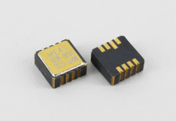
Figure 5: The Model 3038 Accelerometer
is designed for application durability
in extreme temperature, vibration,
and shock environments.
Designed for use in demanding applications and environments, TE Model 3038 is regarded for its excellent durability, high g over-range protection, and long-term stability. For example, it delivers reliable performance at higher altitudes and demanding temperature ranges from -55º to 125ºC while allowing for simple installation with a hermetically sealed SMD design. It incorporates mechanical over-range stops, which enable the sensor to survive up to 10,000-g shock loads while providing precision measurements to ±1.0%. And it includes a gas-damped piezoresistive MEMS sensing element to provide outstanding long-term stability.
Web Links
[1] TE Connectivity, Model 3038 Accelerometer, http://www.te.com/usa-en/product-CAT-EAC0003.html?q=3038&source=header. The Author Bjorn Ryden (Sr. Product Manager, Vibration and Force Sensors) has over 20 years of experience in the sensor industry. He worked at AMETEK Aerospace for over eight years as a Senior Design Engineer where he designed critical sensors for the aerospace industry. Prior to joining TE Connectivity, he worked as a Senior Applications Engineer and Product Manager at Meggitt Sensors. At TE Connectivity for the past 12 years, he has held roles of increasing responsibility within the Product Management team. He holds a BS in Mechanical Engineering from Worcester Polytechnic Institute in Massachusetts, USA. TE Connectivity Ltd. is a $13 billion global technology and manufacturing leader creating a safer, sustainable, productive, and connected future. For more than 75 years, our connectivity and sensor solutions, proven in the harshest environments, have enabled advancements in transportation, industrial applications, medical technology, energy, data communications, and the home. With 78,000 employees, including more than 7,000 engineers, working alongside customers in nearly 150 countries, TE ensures that EVERY CONNECTION COUNTS. Learn more at www.te.com and on LinkedIn, Facebook, WeChat, and Twitter.
Elektor Magazine has been one of the leading sources of information on electronics for engineers, designers, start-ups and companies for 65 years. Our magazine is powered by an active community of electronics engineers – from students to professionals – who are passionate about designing and sharing innovative ideas.
For them, we publish hundreds of items a year, in formats such as articles, videos, webinars, and other learning formats. Our mission is to share knowledge in every possible way and inspire readers with the latest developments within the electrical engineering sector.
Thank you for your vote!
Leave further comments in the fields below.
Thank you for your vote!
If you wish to leave a comment with your rating, please first use the login below. If not, just close this window.


 Bjorn Ryden (Sr. Product Manager, Vibration and Force Sensors) has over 20 years of experience in the sensor industry. He worked at AMETEK Aerospace for over eight years as a Senior Design Engineer where he designed critical sensors for the aerospace industry. Prior to joining TE Connectivity, he worked as a Senior Applications Engineer and Product Manager at Meggitt Sensors. At TE Connectivity for the past 12 years, he has held roles of increasing responsibility within the Product Management team. He holds a BS in Mechanical Engineering from Worcester Polytechnic Institute in Massachusetts, USA.