Elektor community members have always loved audio projects. This Mini VHF FM Receiver project from 2009 presented a complete receiver circuit that boasted excellent reception and sound quality. Let’s take a closer look at the design.
Elektor community members have always loved audio projects. This Mini VHF FM Receiver project from 2009 presented a complete receiver circuit that boasted excellent reception and sound quality. Let’s take a closer look at the design.
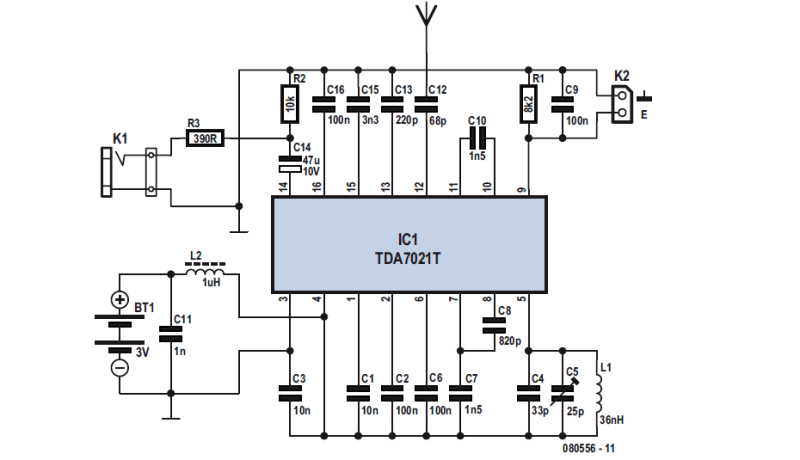
VHF FM Receiver Circuit
The primary challenge was that the integrated circuit (IC) used was only available in a 16-pin SMD package, which could complicate assembly. To simplify construction, Ton Giesberts (Elektor Labs) developed a small PCB specifically for this project, which came from an idea by Karl Odenthal. Additionally, to maintain a compact overall size, the rest of the circuit utilized SMD components, predominantly of the 0805 size. The dimensions of this miniature PCB were impressively small, measuring just 3.2 × 2.7 cm. The circuit design avoided complex coils, and the only requirement was a voltage-controlled oscillator (VCO) that needed an air-cored inductor with a mere four turns.
The receiver consists only of the IC and a few passive components
The complete circuit for the FM receiver was virtually identical to the test circuit shown in the datasheet for the IC, because it was difficult to improve even a little without adding a lot of additional electronics. A few resistors and capacitors plus a coil were required, the Labs Team explained.
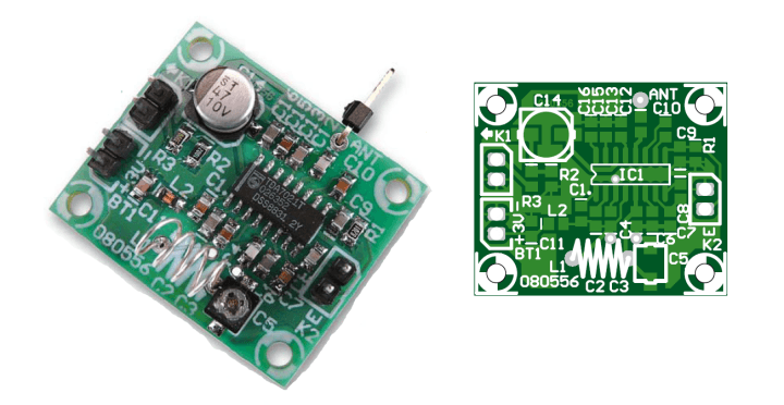
Refer to the compact PCB that was designed for the receiver. The designers used SMD parts everywhere to keep the dimensions as small as possible.
The receiver has a tiny circuit board.
“The inductor for the VCO is an air-cored coil with 4 turns,” the designers explained. “It is best if you use silver-plated wire for this. The easiest way is to wind 4 turns on a 4-mm drill and then stretch the coil slightly until the ends of the coil line up exactly with their respective mounting holes in the PCB. Place the coil a few millimetres above the board, so that you can easily adjust it slightly later on (by stretching or compressing) so that the tuning circuit correctly covers the entire VHF FM broadcast band from 88 to 108 MHz. Tuning is done with trimmer capacitor C5. This does, however, require a small screwdriver and a little patience, but you generally tend to listen to one and the same radio station anyway.”
More About Radio and the Receiver
The Elektor article (080556) associated with this FM receiver project appeared in Elektor February 2009. Elektor Members benefit from the Elektor Mag, an Elektor Store discount, and full access to Elektor’s online library, which includes this article and decades of other editions. Become a member today!
Subscribe
Tag alert: Subscribe to the tag Wireless & Communication and you will receive an e-mail as soon as a new item about it is published on our website!
Elektor Magazine has been one of the leading sources of information on electronics for engineers, designers, start-ups and companies for 65 years. Our magazine is powered by an active community of electronics engineers – from students to professionals – who are passionate about designing and sharing innovative ideas.
For them, we publish hundreds of items a year, in formats such as articles, videos, webinars, and other learning formats. Our mission is to share knowledge in every possible way and inspire readers with the latest developments within the electrical engineering sector.
Thank you for your vote!
Leave further comments in the fields below.
Thank you for your vote!
If you wish to leave a comment with your rating, please first use the login below. If not, just close this window.


Discussion (0 comments)