
Elektor Lab Notes 14: Ongoing projects, DC loads, 4G/5G and more
on

Saad Imtiaz (Senior Engineer, Elektor)
Exciting Developments in Energy Metering and Modular Measurement Projects
ESP32 Energy Meter Update: The PCB has finally arrived, and everything is working as expected! In the upcoming edition of Elektor Magazine, I'll provide an in-depth update on the project. In short, I've integrated the ESP32 Energy Meter with Home Assistant, and it has found its way to my circuit breaker box, providing accurate and detailed readings. As part of the development plan, a specific firmware is being created to leverage the capabilities of the energy metering chip and the advanced AI features of the ESP32-S3. Although this tailored firmware development is time-consuming and still underway, the energy meter remains fully functional with existing platforms like Home Assistant, offering an immediate solution for energy monitoring.


However, I encountered a significant issue with the ATM90E32S Energy Metering Chip. I ordered the chip from a Chinese supplier for cost and delivery speed reasons, but it didn't work at all. Initially, I suspected noise in the circuit due to layout or other factors, but when I sourced the IC directly from Mouser, everything worked perfectly on both the old and new designs. The latest design includes additional noise reduction and insulation measures. The takeaway? Always source your ICs from reputable distributors like Mouser and Digi-Key to avoid such pitfalls.
AmpVolt Project Update: The AmpVolt project has been completed, and everything is working as expected. The module successfully measures up to 50V and 5A. One challenge we faced was the non-linearity of the INA169 at currents between 0.01A and 0.5A, which can be addressed with curve fitting. Overall, this module proves to be a very useful, go-to solution for any type of current and voltage measurement.

With Part One of the project done, we're now focusing on Part Two: designing an expansion board with extra I/O and connectors for the Seeed Studio XIAO line. This board will feature six I2C connections, seven I/Os, and power connectors, aligning with the Grove and Qwiic ecosystems. The expansion board will act as an application controller, collecting sensor data and sending it to the main or host controller via UART, I2C, or even the ESPNOW protocol.
Summer Circuit Edition: Electronic Load Project: For the upcoming Summer Circuit Edition, I've been developing an electronic load using a MOSFET controlled by an ESP32S3. This project was inspired by the need for a dynamic, high-current load to test the AmpVolt project, as my lab lacked electronic load equipment beyond resistive loads. With this electronic load, I achieved up to 8 amps for short periods, keeping things safe due to the inadequate heat sink and cooling solution. Despite this limitation, the circuit is a valuable tool for labs without dynamic loads.

Jean-François Simon (Engineer, Elektor)
PICkit problems... and solutions: It's been a while since I last used my PICkit to program a PIC microcontroller from Microchip. I found a nice project online and wanted to experiment with it. It turns out that the project is quite old and the author programmed it in assembler. The latest version of MBLAB X that supports MPASM is version 5.35, but I've already had problems with this version on my PC, so I prefer version 5.2. Problem: the PICkit is not recognized, with the error message: “Connection failed.” The PICkit was also not recognized by the PICkit Standalone Software: “PICkit3 not found”.
Normally, when switching from MPLAB to Standalone software or vice versa, the software flashes the PICkit firmware before it can program the PIC itself. Standalone software also contains a “Revert to MPLAB mode” option. Somehow, the internal firmware seems to have been corrupted, and the PICkit is no longer recognized. Fortunately, I discovered the PICkitMinus software, developed by Jaakko Kairus from Finland. This little piece of software, based both on open source code provided by Microchip and on the work of Evan from PICkitPlus (a similar project) was designed to use your trusty old PICkit2 and PICkit3 with newer Microchip PIC microcontrollers that would otherwise not be supported. This software correctly detected the PICkit, and allowed me to “Revert to MPLAB mode” successfully. Hurray!

SD card reliability issues: while working on an Arduino-based data logger and SD card, I encountered reliability issues. The SD cards would suddenly become unreadable by the PC. I found the source of the problem: in my tests, I inadvertently cut the power too soon after the last write operation. While browsing forums, I realized that this was a well-known problem. Indeed, when building a battery-powered recorder, you can put the microcontroller into deep sleep to save power, but the SD card in standby continues to draw a current of around 100 µA (more or less depending on the manufacturer).
To avoid this, some users completely shut off the SD card's power supply, using a PNP transistor on the positive power rail, for example. But, as summarized by Bill Greiman (the author of the SdFat library for Arduino), “[the SD Standard] says that reliably removing power is not supported in SPI mode. It does suggest that you can remove power one second after the card goes not busy but does not guarantee this will work.” I found an interesting article about reducing power consumption of SD cards.
To improve the reliability of SD cards, we also need to limit the number of writes, and write chunks (as large as possible) to the card. This can be achieved by storing values in SRAM (such as Microchip's 23LCV series) or FRAM, and writing to the SD card less frequently.

Lattice iCEcube2 is free again: A few weeks ago, I decided to take a look at Russell Merrick's book Getting Started with FPGAs. What a surprise to find that iCEcube2, the development environment used to program the iCE40 HX1K used in the book's tutorials was no longer free, but would now require a $471/year license, as reported by outraged users on Reddit and the EEVBlog. Fortunately, Lattice has listened to the protests, and now offers a free license for hobbyists, enthusiasts, community educators & start-up companies. It's not as good as if it had remained free for everyone as before, but at least the worst has been avoided. Thanks to the community for notifying Lattice of the problem in such large numbers, and thanks to Lattice for listening!

Roberto Armani (Senior Editor, Elektor Magazine)
Plenty of articles in preparation nowadays!
- 5G interview is ready! How's going with the transition from 4G to 5G? Do you want to know more about 4 and 5G frequencies used worldwide, on the development phases of this shift and how far the providers came with their implementation?
You'll read all this in the next July–August Issue, stay tuned!

- Summer circuit edition: Pimp My Car Battery Charger three projects. For the next Summer circuit Edition, lead-acid batteries will be under the spotlight in this article, written jointly with Walter Ribbert.
What happens in charging a battery with the state-of-the-art devices? And with some less sophisticated appliances?
How can we assess the internal resistance of an accumulator?
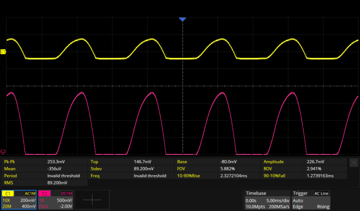
Below, you see the scope screenshot of the start-of-charge phase of a 12 V, 52 Ah battery. The red trace represents the output of an in-circuit Pico TA018 DC current clamp (100 mV/A) indicating charging current peaks of 18.5 A @ 100 Hz, whilst the yellow trace (coupled in AC) displays the ripple (253 mV) measured at the battery clamps through separated sense wires. These readouts allows us to calculate an internal resistance Ri = 13.6 mΩ, not bad for a used accumulator.

Discussion (1 comment)